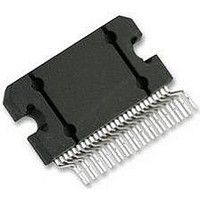
LM4780TA National Semiconductor, LM4780TA Datasheet - Page 20

LM4780TA
Manufacturer Part Number
LM4780TA
Description
Audio Power Amplifier IC
Manufacturer
National Semiconductor
Datasheet
1.LM4780TA.pdf
(26 pages)
Specifications of LM4780TA
Amplifier Case Style
TO-220
Peak Reflow Compatible (260 C)
No
Termination Type
Through Hole
Leaded Process Compatible
No
Package / Case
27-TO-220
Operational Class
Class-AB
Audio Amplifier Output Configuration
1-Channel Mono/2-Channel Stereo
Output Power (typ)
120x1/60x2@8OhmW
Audio Amplifier Function
Speaker
Input Offset Voltage
10mV
Input Bias Current
1uA
Total Harmonic Distortion
0.03@4Ohm@30W%
Single Supply Voltage (typ)
18V
Dual Supply Voltage (typ)
±12/±15/±18/±24/±28V
Power Supply Requirement
Single/Dual
Power Dissipation
125W
Unity Gain Bandwidth Product (typ)
8MHz
Rail/rail I/o Type
No
Power Supply Rejection Ratio
120dB
Single Supply Voltage (min)
20V
Single Supply Voltage (max)
84V
Dual Supply Voltage (min)
±10V
Dual Supply Voltage (max)
±42V
Operating Temp Range
-20C to 85C
Operating Temperature Classification
Commercial
Mounting
Through Hole
Pin Count
27 +Tab
Package Type
TO-220
Lead Free Status / RoHS Status
Contains lead / RoHS non-compliant
Lead Free Status / RoHS Status
Contains lead / RoHS non-compliant
Available stocks
Company
Part Number
Manufacturer
Quantity
Price
Part Number:
LM4780TA L4780TA
Manufacturer:
NS/国半
Quantity:
20 000
Company:
Part Number:
LM4780TA/NOPB
Manufacturer:
TI
Quantity:
560
www.national.com
The load current I
I
Therefore the voltage appearing at the non-inverting input is
effectively positive feedback and the circuit may oscillate. If
there was only one device to worry about then the values of
R
however, several devices normally comprise a total system.
Any ground return of a separate device, whose output is in
phase, can feedback in a similar manner and cause instabil-
ities. Out of phase ground loops also are troublesome, caus-
ing unexpected gain and phase errors.
The solution to most ground loop problems is to always use
a single-point ground system, although this is sometimes im-
practical. The third figure above is an example of a single-
point ground system.
The single-point ground concept should be applied rigorously
to all components and all circuits when possible. Violations of
I
, thus V
1
and R
1
2
will follow the output voltage directly, i.e. in phase.
would probably be small enough to be ignored;
L
will be much larger than input bias current
20058698
20
single-point grounding are most common among printed cir-
cuit board designs, since the circuit is surrounded by large
ground areas which invite the temptation to run a device to
the closest ground spot. As a final rule, make all ground re-
turns low resistance and low inductance by using large wire
and wide traces.
Occasionally, current in the output leads (which function as
antennas) can be coupled through the air to the amplifier in-
put, resulting in high-frequency oscillation. This normally hap-
pens when the source impedance is high or the input leads
are long. The problem can be eliminated by placing a small
capacitor, C
LM4780 input terminals. Refer to the External Components
Description section relating to component interaction with
C
REACTIVE LOADING
It is hard for most power amplifiers to drive highly capacitive
loads very effectively and normally results in oscillations or
ringing on the square wave response. If the output of the
LM4780 is connected directly to a capacitor with no series
resistance, the square wave response will exhibit ringing if the
capacitance is greater than about 0.2μF. If highly capacitive
loads are expected due to long speaker cables, a method
commonly employed to protect amplifiers from low
impedances at high frequencies is to couple to the load
through a 10Ω resistor in parallel with a 0.7μH inductor. The
inductor-resistor combination as shown in the
lates the feedback amplifier from the load by providing high
output impedance at high frequencies thus allowing the 10Ω
resistor to decouple the capacitive load and reduce the Q of
the series resonant circuit. The LR combination also provides
low output impedance at low frequencies thus shorting out the
10Ω resistor and allowing the amplifier to drive the series RC
load (large capacitive load due to long speaker cables) di-
rectly.
INVERTING AMPLIFIER APPLICATION
The inverting amplifier configuration may be used instead of
the more common non-inverting amplifier configuration
shown in
THD+N performance and eliminates the need for a large ca-
pacitor (Ci) reducing cost and space requirements. The val-
ues show in
with a gain of 20V/V (Gain = -R
ues, the value of R
tion of R
f
.
f
and Ri.
Figure
C
Figure 6
, (on the order of 50pF to 500pF) across the
1. The inverting amplifier can have better
B
should be eqaul to the parallel combina-
are only one example of an amplifier
f
/R
i
). For different resistor val-
Figure 5
iso-


