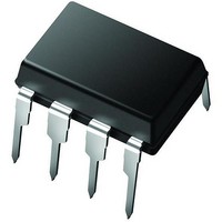
PIC12C672-10/P Microchip Technology, PIC12C672-10/P Datasheet - Page 444

PIC12C672-10/P
Manufacturer Part Number
PIC12C672-10/P
Description
IC,MICROCONTROLLER,8-BIT,PIC CPU,CMOS,DIP,8PIN,PLASTIC
Manufacturer
Microchip Technology
Series
PIC® 12Cr
Datasheets
1.PIC16F688T-ISL.pdf
(688 pages)
2.PIC12CE673-10P.pdf
(129 pages)
3.PIC12CE673-10P.pdf
(14 pages)
Specifications of PIC12C672-10/P
Rohs Compliant
YES
Core Processor
PIC
Core Size
8-Bit
Speed
10MHz
Peripherals
POR, WDT
Number Of I /o
5
Program Memory Size
3.5KB (2K x 14)
Program Memory Type
OTP
Ram Size
128 x 8
Voltage - Supply (vcc/vdd)
3 V ~ 5.5 V
Data Converters
A/D 4x8b
Oscillator Type
Internal
Operating Temperature
0°C ~ 70°C
Package / Case
8-DIP (0.300", 7.62mm)
Processor Series
PIC12C
Core
PIC
Data Bus Width
8 bit
Data Ram Size
128 B
Maximum Clock Frequency
10 MHz
Number Of Programmable I/os
5
Number Of Timers
1
Operating Supply Voltage
3 V to 5.5 V
Maximum Operating Temperature
+ 70 C
Mounting Style
Through Hole
3rd Party Development Tools
52715-96, 52716-328, 52717-734
Development Tools By Supplier
ICE2000
Minimum Operating Temperature
0 C
On-chip Adc
8 bit, 4 Channel
Lead Free Status / RoHS Status
Lead free / RoHS Compliant
For Use With
ISPICR1 - ADAPTER IN-CIRCUIT PROGRAMMINGAC124001 - MODULE SKT PROMATEII 8DIP/SOIC
Eeprom Size
-
Connectivity
-
Lead Free Status / Rohs Status
Details
- Current page: 444 of 688
- Download datasheet (3Mb)
PICmicro MID-RANGE MCU FAMILY
24.1
DS31024A-page 24-2
AN15
AN14
AN13
AN12
AN11
(SLPCON<0>)
AN7
AN6
AN5
AN4
AN3
AN2
AN1
AN0
Note 3
ADOFF
Bandgap Ref.
OSC1
Oscillator
AN0
Internal
SREFLO
CDAC
Introduction
SREFHI
C
(Configuration Bit)
~2.5uA~5uA~10uA~20uA
FOSC
0
1
The components required to create a Slope A/D converter include:
• Precision comparator
• 4-bit programmable current source
• 16-channel analog MUX
• 16-bit timer with capture register
This section will discuss using these components for a Slope A/D.
Each analog input channel is multiplexed to a single analog input source to be converted by
means of a slope conversion method (using a single precision comparator). The programmable
current source feeds an external capacitor to generate the ramp voltage used in the conversion.
Figure 24-1: Slope A/D Block Diagram
ADCON0<7:4>
~100
14
12
11
15
13
10
9
8
7
6
5
4
3
2
1
0
ADCON1<7:4>
4-Bit Current DAC (Note 1)
(ADCON0<2>)
Analog
MUX
~ 1 k
4
AMUXOE
ADRST (ADCON0<1>)
ADOFF
ADRST
Note 2
ADOFF
Slope A/D
Capture Interrupt (ADCIF)
Clock
Logic
Stop
Slope A/D Capture
Note 1: All current sources are disabled if ADRST = ‘1’
ADTMRH
ADCAPH
2: Approximately 3.5 microsecond time constant
3: Dependent on A/D resolution and input voltage
range (see
ADTMRL
ADCAPL
Table
24-2)
Overflow
1997 Microchip Technology Inc.
Timer
Internal
Data
Bus
Related parts for PIC12C672-10/P
Image
Part Number
Description
Manufacturer
Datasheet
Request
R

Part Number:
Description:
IC MCU OTP 2KX14 A/D 8DIP
Manufacturer:
Microchip Technology
Datasheet:

Part Number:
Description:
IC MCU OTP 2KX14 A/D 8-SOIJ
Manufacturer:
Microchip Technology
Datasheet:

Part Number:
Description:
IC MCU OTP 2KX14 A/D 8-SOIJ
Manufacturer:
Microchip Technology
Datasheet:

Part Number:
Description:
IC MCU OTP 2KX14 A/D 8-SOIJ
Manufacturer:
Microchip Technology
Datasheet:

Part Number:
Description:
IC MCU OTP 2KX14 A/D 8DIP
Manufacturer:
Microchip Technology
Datasheet:

Part Number:
Description:
IC MCU OTP 2KX14 A/D 8-SOIJ
Manufacturer:
Microchip Technology
Datasheet:

Part Number:
Description:
IC MCU OTP 2KX14 A/D 8DIP
Manufacturer:
Microchip Technology
Datasheet:

Part Number:
Description:
IC MCU OTP 2KX14 A/D 8DFN
Manufacturer:
Microchip Technology
Datasheet:

Part Number:
Description:
IC PIC MCU 2KX14 8DFN
Manufacturer:
Microchip Technology
Datasheet:

Part Number:
Description:
IC MCU OTP 2KX14 A/D 8-SOIJ
Manufacturer:
Microchip Technology
Datasheet:

Part Number:
Description:
IC MCU OTP 2KX14 A/D 8DFN
Manufacturer:
Microchip Technology
Datasheet:

Part Number:
Description:
IC MCU OTP 2KX14 A/D 8DIP
Manufacturer:
Microchip Technology
Datasheet:

Part Number:
Description:
IC MCU OTP 2KX14 A/D 8-SOIJ
Manufacturer:
Microchip Technology
Datasheet:

Part Number:
Description:
IC MCU EPROM 2KX14 A/D 8CDIP
Manufacturer:
Microchip Technology
Datasheet:

Part Number:
Description:
IC,MICROCONTROLLER,8-BIT,PIC CPU,CMOS,DIP,8PIN,PLASTIC
Manufacturer:
Microchip Technology
Datasheet:


