8502SCO2V02S SQUARE D, 8502SCO2V02S Datasheet - Page 34
8502SCO2V02S
Manufacturer Part Number
8502SCO2V02S
Description
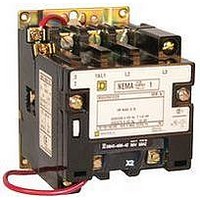
CONTACTOR, 3PST, 120VAC, 27A, PANEL
Manufacturer
SQUARE D
Specifications of 8502SCO2V02S
No. Of Poles
3
Contact Configuration
3PST
Relay Mounting
Panel
Coil Voltage Vac Nom
120V
Relay Terminals
Wire Leaded
Contact Voltage Ac Nom
600V
Contact Current Max
27A
Current, Rating
27 A
Enclosure Type
Open
Horse Power Rating
7.5 @ 230 VAC, 10 @ 480 VAC
Relay Type
Contactor
Standards
UL Listed File E78351 CCN NLDX - CSA Certified File LR60905 Class 3211 04
Termination
Screw Clamp
Voltage, Coil
120 VAC
Voltage, Rating
600 VAC
Operating Voltage
600VAC
Switching Power Ac3
10hp
Switching Current Ac3
27A
Load Current Inductive
27A
Load Current Resistive
27A
Rohs Compliant
No
Lead Free Status / RoHS Status
Contains lead / RoHS non-compliant


5/98
Power Contact Ratings
All contactors are rated in accordance with NEMA
standards. The ratings shown in the tables on
Pages 29-32 are for normal service. For complete
data on power contact ratings, refer to Class 8536
Section.
Maintenance of Equipment
Class 9998 repair parts kits are available for all
Class 8702 contactors and Class 8736 starters.
Service bulletins with a complete list of
replaceable parts are supplied with all devices.
See Page 15.
Control Transformer Selection
The following table gives the proper size control
transformer to be used with a given reversing
device, with or without additional auxiliary
contacts or timer. For factory addition of control
transformers, see Factory Modifications (Forms)
section.
NEMA Size
0, 1 & 2
3
4
5
6 & 7
Additional
Auxiliary
Contacts on
L.H.
Contactor
(Forward
Contactor)
Example: X
Standard
(No Additional
Auxiliary Contacts)
1 N.O.
1 N.C.
2 N.O.
1 N.O.-1 N.C.
2 N.C.
Type
SB, SC & SD
SE
SF
SG
SH & SJ
© 1998 Square D All Rights Reserved
No. of
Poles
Any
3
4 & 5
Any
Any
Any
1
Additional Auxiliary Contacts on R.H. Contactor (Reverse Contactor)
Standard
(No Additional
Auxiliary Contacts)
X1000
X0100
X2000
X1100
X0200
O
Transformers
Class 9070
Type
T100 or GO2
T1500 or GO3
T300
T300
T500
See Page 16
1
O
1 N.O.
X0010
X1010
X0110
X2010
X1110
X0210
Number of N.C. auxiliary contacts on right hand (Reverse) contactor.
Number of N.O. auxiliary contacts on right hand (Reverse) contactor.
Number of N.C. auxiliary contacts on left hand (Forward) contactor.
Number of N.O. auxiliary contacts on left hand (Forward) contactor.
Basic Form Designation.
Auxiliary Units
The table below shows the maximum number of
auxiliary units (in addition to the holding circuit
and interlocking contacts) that can be added to
either the forward or reverse contactor or starter.
Factory Installed Auxiliary Contacts
Additional auxiliary contacts may be factory or
field added to any Type 3 contactor or starter. See
table above for maximum number of auxiliary
units. The table below lists the Form designations
for factory installed auxiliary contacts. See Class
9999 for field modification kits.
NEMA Size
(Type)
00
(SA)
0, 1 & 2
(SB, SC
& SD)
3, 4, 5, 6, & 7
(SE, SF, SG,
SH, & SJ)
q
Application Data – Class 8702, 8736
1 N.C.
X0001
X1001
X0101
X2001
X1101
X0201
When adding 4 external auxiliary contacts to one Size 0 or 1
contactor, remove one of the return springs.
No. of Poles
of Basic
Contactor
2 or 3
2 or 3
4
Any
2 N.O.
X0020
X1020
X0120
X2020
X1120
X0220
Maximum number of
auxiliary units on each
contactor, forward or
reverse, (in addition to
internal holding circuit and
interlocking contacts).
2 single circuit auxiliary contacts
(N.O. or N.C.)
4 single circuit auxiliary contactsq
(N.O. or N.C.)
1 single circuit auxiliary contact
(N.O. or N.C.) plus 1 attached timer
(ON or OFF delay).
2 single circuit auxiliary contacts
(N.O. or N.C.)
2 single circuit auxiliary contacts
(N.O. or N.C.)
1 single circuit auxiliary contact plus
1 attached timer (ON or OFF delay).
1 N.O.-1 N.C.
X0011
X1011
X0111
X2011
X1111
X0211
2 N.C.
X0002
X1002
X0102
X2002
X1102
X0202
33
Related parts for 8502SCO2V02S
Image
Part Number
Description
Manufacturer
Datasheet
Request
R


Part Number:
Description:
Pushbutton, Non-Illum'd Red "STOP", Momentary, 1NO-1NC, Square 30mm, 10A, 600V
Manufacturer:
SQUARE D
Datasheet:

Part Number:
Description:
KITS,TWIDO? PROGRAMMABLE CONTROLLERS,KITS,TWIDOPACK STARTER KIT - ADVANCED LEVEL,PROGRAMMABLE CONTROLLERS,TWIDO? PROGRAMMABLE CONTROLLERS ,SQUARE D
Manufacturer:
SQUARE D

Part Number:
Description:
LAMPS,INDICATOR,STACKABLE,LAMPS, STACKABLE INDICATOR,VISUAL INDICATING SIGNALS,XVB SERIES INDICATING BANKS ,SQUARE D
Manufacturer:
SQUARE D
Part Number:
Description:
LAMPS,INDICATOR,STACKABLE,LAMPS, STACKABLE INDICATOR,VISUAL INDICATING SIGNALS,XVB SERIES INDICATING BANKS ,SQUARE D
Manufacturer:
SQUARE D
Datasheet:
Part Number:
Description:
I/O EXTENDER MODULE 4 D IN & 2 D OUTPUT
Manufacturer:
SQUARE D
Datasheet:
Part Number:
Description:
CB ACCESSORY, UNDERVOLTAGE TRIP 48V DC
Manufacturer:
SQUARE D
Datasheet: