A202K1EAM EATON CUTLER HAMMER, A202K1EAM Datasheet - Page 29
A202K1EAM
Manufacturer Part Number
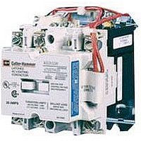
A202K1EAM
Description
Lighting Contactor
Manufacturer
EATON CUTLER HAMMER
Datasheet
1.A202K2CXM.pdf
(40 pages)
Specifications of A202K1EAM
Coil Voltage Vac Nom
120V
Contact Current Max
30A
Mounting Type
DIN Rail
External Height
111.3mm
Continuous Load Current
30A
Peak Reflow Compatible (260 C)
No
External Width
106.4mm
Operating Voltage
600VAC
Switching Current Ac3
30A
Load Current Inductive
30A
No. Of Poles
5
Contactor Direction
Reversing
Relay Mounting
Panel
Rohs Compliant
No
Lead Free Status / RoHS Status
Contains lead / RoHS non-compliant


June 2008
Wiring Diagrams
Figure 37-11. Typical Wiring Diagram — C30CN
CA08102001E
Figure A
START/STOP Pushbuttons
Figure B
START/STOP
Selector Switch
Figure D
2 Position
Selector Switch
Remove wire “C” when it is supplied. Connect separate
control lines to #1 terminal on the remote pilot device,
and to the #96 terminal on the overload relay.
SEPARATE CONTROL
Omit this
connector
if Figure 2
Is Used
Transformer
See Figure 2
2/13
3/14
3
4
(If Used)
Control
Fusible
1
2
1
CPT
Red
Blk
Yel
1
2
1
3
Figure 1 – Front View Diagram
4
Start (On)
OL
Hand
M
T1
Yel
Red
Auto
2
Start (On)
Stop (Off)
Blk
Red
Blk
L1
L1
T1
Disconnecting
1
2
D.S. or C.B.
3
1
T1
3/14
1
Means
A1
T2
1
3/14
Motor
4
4
2
T2
L2
L2
T2
3
4
A2
T3
T3
6
Local Control
L3
L3
T3
Figure F
START–STOP with Pilot Light
Figure C
3 Position Selector Switch
Figure E
Pilot Light (Motor Run)
5
6
Start (On)
Stop (Off)
3
4
4
2
“C”
X1
X2
Reset
2/13
3/14
98
97
96
95
COMBINATION MOTOR CONTROLLER
3
4
Hand
3
1
Yel
Connections for Control Stations
Auto
Red
X1
X2
Blk
Local
Control
(Flange-
Mounting
If Used)
See
Figures
A, B, C,
D, E & F
Connections for Starters
3/14
1
Blk/Wht
Blk/Wht
Remote
Blk/Wht Connect
Blk/Wht
2/13
3/14
1
Switch
For more information visit: www.eaton.com
Connect
to Coil
Terminals
A1 & A2
Connections for dual
voltage rated transformer –
see transformer nameplate.
Remove wire “C” (Figure 1) if used and connect as
shown below. (All other starter wires remain as shown
in Figure 1.)
Lighting Contactors
UL Rated AC Contactors
Wiring Diagrams
to Coil
Terminals
A1 & A2
H2
H3
Terminal
4
1
To Coil
H4
A1
OL
Figure 2 – Fusible Control Transformer
M
T1
2
L1
T1
T1
H1
1
X2
Field Conversion to 1 Phase
Omit Connector
A1
X1
XF
T2
3 Wire Control
Motor
2 Wire Control
Not for use with auto reset OL relays.
When more than one pushbutton
station is used, omit connector “A”
and connect per sketch below.
4
Remote
L2
3
Start
G
Stop
Combined Remote and Local
A2
CPT
1
T3
Start
Stop
6
T2
T2
L3
(For Figures 1 & 2)
5
Remote Control
2/13
“A”
M
L1
1
A1 A2
L2
Add Dotted
Connection
3
Start
Stop
Start (On)
Stop (Off)
Start
Stop
4
2
Primary
Connections
Local
L3
5
Connections
Secondary
3
1
3/14
2/13
1
OL
3/14
1
3/14
2/13
1
Reset
96
95
3/14
1
* If common control 1 to L1/X2 to
1
ON/OFF Pushbuttons (Momentary)
1
1
ON/OFF Pushbuttons (Maintained)
HAND/OFF/AUTO Selector Switch
Red
Red
Line
Contacts
L2. See Pub. 50774 if CPT is
required.
Red
Aux.
Electrically Held Contactor
L10
L12
Hand
Optional Pilot Devices for
C30CN WIRING DIAGRAM
L2
L4
L6
L8
*Separate Source
*Separate Source
*Separate Source
C30CNE Electrically Held
Yellow
L11
Yellow
Off
Off
L1
L3
L5
L7
L9
Off
A1
On
On
Auto
C
Yellow
Coil
C
C
C
Black
Black
3
3
3
(A1)
(A1)
(A1)
A2
1
2
3
4
5
6
7
7
7
Contacts
T11
T1
T3
T5
T7
T9
On
On
On
Aux.
R
C
R
C
R
C
T10
T12
T2
T4
T6
T8
Off
Off
Off
G
G
G
Load
(A2)
(A2)
(A2)
X2
X2
X2
37-29
37
Related parts for A202K1EAM
Image
Part Number
Description
Manufacturer
Datasheet
Request
R

Part Number:
Description:
PROGRAMMABLE LOGIC CONTROLLER
Manufacturer:
EATON CUTLER HAMMER
Part Number:
Description:
Pm Power Pro 3000/5000 A-B Accel/On Interface
Manufacturer:
EATON CUTLER HAMMER
Part Number:
Description:
Handle Tie Bar For (2) - 1 Pole Type BR Breakers
Manufacturer:
EATON CUTLER HAMMER
Part Number:
Description:
Type CH Breaker 150A/2 Pole 120/240V 10K
Manufacturer:
EATON CUTLER HAMMER
Part Number:
Description:
Tenant Branch Breaker 125A/3 Pole 120/240V 42K
Manufacturer:
EATON CUTLER HAMMER
Part Number:
Description:
Type CL Breaker 25A/1Pole 120/240V 10K-Classified 1" Ckt Bkr
Manufacturer:
EATON CUTLER HAMMER
Part Number:
Description:
FD BREAKER 1P 80 AMP WITH LOAD ONLY TERMINALS
Manufacturer:
EATON CUTLER HAMMER
Part Number:
Description:
GD 2 POLE BREAKER, 25 AMP, SINGLE PACKED
Manufacturer:
EATON CUTLER HAMMER
Part Number:
Description:
Handle Tie Bar For (2) - 1 Pole Type BR Breakers
Manufacturer:
EATON CUTLER HAMMER
Part Number:
Description:
Type CL Breaker 25A/1Pole 120/240V 10K-Classified 1" Ckt Bkr
Manufacturer:
EATON CUTLER HAMMER