C30CNE20A0 EATON CUTLER HAMMER, C30CNE20A0 Datasheet - Page 4
C30CNE20A0
Manufacturer Part Number
C30CNE20A0
Description
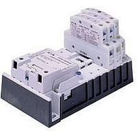
Lighting Contactor
Manufacturer
EATON CUTLER HAMMER
Datasheet
1.A202K2CXM.pdf
(40 pages)
Specifications of C30CNE20A0
No. Of Poles
2
Contact Configuration
DPST-NC
Relay Mounting
DIN Rail
Coil Voltage Vac Nom
120V
Contact Current Max
30A
Mounting Type
DIN Rail
External Height
187.6mm
Continuous Load Current
30A
Operating Voltage
600VAC
Switching Current Ac1
30A
Switching Current Ac3
30A
Load Current Inductive
30A
Contactor Direction
Reversing
Rohs Compliant
No
Lead Free Status / RoHS Status
Contains lead / RoHS non-compliant


37
37-4
Auxiliary Contact Location
Auxiliary Contacts — Mounting Positions
The sketches below illustrate the maxi-
mum number of auxiliary contacts that
can be assembled to a contactor and
their locations in standard enclosures.
Table 37-6. Auxiliary Contact Mounting Positions
Figure 37-1. Auxiliary Contact Location
Size
100 Ampere
200 Ampere
300 Ampere
400 Ampere
10 Ampere
20 – 60 Ampere
60 Ampere
60 Ampere
Available positions on contactors or starters other than what is factory installed.
When a pneumatic timer is mounted on contactor, only side mounted auxiliary contact positions
are available. The solid-state timer, when added, takes up side mounted auxiliary contact
position.
For 100 – 400A contactors, a base auxiliary contact must be added in position L1 before additional
contacts can be mounted.
Lighting Contactors
Open Control
CN35 Electrically Held
Cont.
Base
Aux.
L1
of Contactor
Left Side
L1
Poles
2 – 4
2 – 3
4
5
2 – 3
2 – 3
2 – 3
2 – 3
Cont.
Aux.
L2
Top View
T1
Cont.
Aux.
L3
Available Mounting Positions
Open Type
T1, L1, R1
T1, L1
T1, L1
T1, L1
R2, R3, L1, L2, L3
R2, R3, L1, L2, L3
R2, R3, L1, L2, L3
R2, R3, L1, L2, L3
R1
of Contactor
Contactors
Contactors
100 – 400A
10 – 60A
Front
For more information visit: www.eaton.com
NEMA 1
L1
L1
—
—
R2, R3, L1, L2, L3
R2, R3, L1, L2, L3
R2, R3, L1, L2, L3
R2, R3, L1, L2, L3
L1
Cont.
Aux.
Front View
R3
of Contactor
Right Side
T1
Cont.
Aux.
R2
R1
Cont.
Base
Aux.
R1
NEMA 3R,
4X, 12
L1, T1
L1, T1
L1, T1
L1, T1
R2, R3, L1, L2, L3
R2, R3, L1, L2, L3
R2, R3, L1, L2, L3
R2, R3, L1, L2, L3
Pneumatic Timers — Top Mounted
Attachment mounts on top of 10 – 60A
lighting contactors (top mounted aux-
iliary contacts can not be installed on
device when timer is used). Timer unit
has DPST timed contacts — circuits in
each pole must be the same polarity.
Units are convertible from OFF to ON
Delay or vice-versa.
Table 37-7. Pneumatic Timers
Table 37-8. Maximum Ampere Ratings
Discount Symbol . . . . . . . . . . . . . . . . . . . . . . 1CD-1C
Timing Range
.1 to 30 Seconds
10 to 180 Seconds
Description
Make
Break
Pneumatic Timer
Volts AC
120
30.0
3.0
Catalog
Number
C320TP1
C320TP2
15.0
240
1.5
480
7.5
0.75
CA08102001E
Price
U.S. $
June 2008
600
6.0
0.6
Related parts for C30CNE20A0
Image
Part Number
Description
Manufacturer
Datasheet
Request
R

Part Number:
Description:
PROGRAMMABLE LOGIC CONTROLLER
Manufacturer:
EATON CUTLER HAMMER
Part Number:
Description:
Pm Power Pro 3000/5000 A-B Accel/On Interface
Manufacturer:
EATON CUTLER HAMMER
Part Number:
Description:
Handle Tie Bar For (2) - 1 Pole Type BR Breakers
Manufacturer:
EATON CUTLER HAMMER
Part Number:
Description:
Type CH Breaker 150A/2 Pole 120/240V 10K
Manufacturer:
EATON CUTLER HAMMER
Part Number:
Description:
Tenant Branch Breaker 125A/3 Pole 120/240V 42K
Manufacturer:
EATON CUTLER HAMMER
Part Number:
Description:
Type CL Breaker 25A/1Pole 120/240V 10K-Classified 1" Ckt Bkr
Manufacturer:
EATON CUTLER HAMMER
Part Number:
Description:
FD BREAKER 1P 80 AMP WITH LOAD ONLY TERMINALS
Manufacturer:
EATON CUTLER HAMMER
Part Number:
Description:
GD 2 POLE BREAKER, 25 AMP, SINGLE PACKED
Manufacturer:
EATON CUTLER HAMMER
Part Number:
Description:
Handle Tie Bar For (2) - 1 Pole Type BR Breakers
Manufacturer:
EATON CUTLER HAMMER
Part Number:
Description:
Type CL Breaker 25A/1Pole 120/240V 10K-Classified 1" Ckt Bkr
Manufacturer:
EATON CUTLER HAMMER