841CS2-UNI Magnecraft / Schneider Electric, 841CS2-UNI Datasheet - Page 2
841CS2-UNI
Manufacturer Part Number
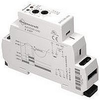
841CS2-UNI
Description
CURRENT SENSING RELAY, SPDT, 0.2-2A
Manufacturer
Magnecraft / Schneider Electric
Series
841r
Specifications of 841CS2-UNI
Contact Configuration
SPDT
Power Consumption
1.5VA
Supply Voltage Max
240VAC
Supply Current Max
2A
Relay Mounting
DIN Rail
Control Voltage
240VAC
Coil Voltage Vac Nom
240V
Display Type
Time-Delay Relay
Supply Voltage
24 V to 240 V
Contact Form
SPDT
Termination Style
Quick Connect
Function
Current
Output
Current
Range, Measurement
2 A
Technology
Inductive
Voltage, Supply
24-240 VAC
No. Of Poles
1
Rohs Compliant
Yes
Carry Current
2A
Lead Free Status / RoHS Status
Lead free / RoHS Compliant


M ag n e cr a f t S olu t i o n G ui de 10 5A
Function
A.
ON DELAY
Power On
B.
REPEAT
CYCLE
Starting Off
C.
INTERVAL
Power On
D.
OFF DELAY
S Break
E.
RETRIGGERABLE
ONE SHOT
F.
REPEAT
CYCLE
Starting On
G.
PULSE
GENERATOR
H.
ONE SHOT
I.
ON/OFF
DELAY
S Make/Break
J.
MEMORY
LATCH
S Make
U = Input Voltage
FUNCTION DEFINITION TABLES
Operation
When the input voltage U is applied, timing delay t begins. Relay contacts R
change state after time delay is complete. Contacts return to their shelf state
when power U is removed. Control switch is not used in this mode.
When input voltage U is applied, time delay t begins. When time delay t is
complete, relay contact R change state for time delay t. This cycle will repeat
until input voltage U is removed. Control switch is not used in this mode.
When input voltage U is applied, relay contacts R change state immediately
and timing cycle begins. When time delay is complete, contacts return to shelf
state. When input voltage U is removed, contacts return to their shelf state.
Control switch is not used in this mode.
Input voltage U must be applied continuously. When control S is closed, relay
contacts R change state. When control S is opened delay t begins. When delay t
is complete, contact R return to their shelf state. If signal S is closed before time
delay t is complete, then time is reset, the delay begins again, and relay contacts
remain in their energized state If input voltage U is removed, relay contact R
return to their shelf state.
Upon application of input voltage U, the time delay relay is ready to accept
trigger signals S. Upon application of the trigger signal S, the relay contacts R
transfer and the preset time t begins. At the end of the preset time t, the relay
contacts R return to their normal condition unless the trigger signal S is opened
and closed prior to time out t (before preset time elapses). Continuous cycling of
the trigger signal S at a rate faster than the preset time will cause the relay
contacts R to remain closed.
When input voltage U is applied, relay contacts R change state immediately and
time delay t begins. When time delay t is complete, contacts return to their shelf
state for time delay t. This cycle will repeat until input voltage U is removed.
Control switch is not used in this mode.
Upon application of input voltage U, a single output pulse of 0.5 seconds long
is delivered to relay after time delay t. Power must be removed and reapplied
to repeat pulse. Control switch S is not used in the mode.
Upon application of input voltage U, the time delay relay is ready to accept
trigger signals S. Upon application of the trigger signal S, the relay contacts R
transfer and the preset time t begins. During time-out, the trigger signal S is
ignored. The time delay relay resets by applying the trigger signal S when the
relay is not energized.
Input voltage U must be applied continuously. When control S is closed, time
delay t begins. When time delay t is complete, relay contacts R change state
and remain transferred until control S is opened. If input power U is removed
relay contacts R return to their shelf state.
Input voltage U must be applied continuously. Output changes state with every
control S closure. Returned to rest condition when power is removed.
S = Control Switch
R = Relay Contacts
t = Time Delay
U
U
R
U
R
U
R
U
S
R
U
S
R
R
U
R
U
S
R
U
S
R
U
S
R
Timing Chart
close
open
close
open
close
open
close
open
close
open
on
off
on
off
on
off
on
off
on
off
on
off
on
off
on
off
on
off
t
t
t
t
t
t
t
t
Pulse
t
t
t
t
t
t
t
t
t
t
t
t
t
t
t
Pulse
t
t
t
t
t
5/3
Related parts for 841CS2-UNI
Image
Part Number
Description
Manufacturer
Datasheet
Request
R

Part Number:
Description:
Solid State Relays 3A/50VAC SPST-NO
Manufacturer:
Magnecraft / Schneider Electric
Datasheet:

Part Number:
Description:
HEAT SINK MAGNECRAFT
Manufacturer:
Magnecraft / Schneider Electric
Datasheet:

Part Number:
Description:
Bracket, Panel Mounting; Use with 711, 712, TDRSRX/SOX Series Magnecraft Relays
Manufacturer:
Magnecraft/Schneider Electric
Datasheet:
Part Number:
Description:
Bracket, DIN Rail Mounting; Use with 711, 712, TDRSRX/SOX Series Magnecraft Relays
Manufacturer:
Magnecraft/Schneider Electric
Datasheet:

Part Number:
Description:
Solid State Relays SPST-NO 48 to 480 VAC
Manufacturer:
Magnecraft / Schneider Electric
Datasheet:
Part Number:
Description:
Solid State Relays SPST-NO 48 to 480 VAC
Manufacturer:
Magnecraft / Schneider Electric
Datasheet:
Part Number:
Description:
Solid State Relays SPST-NO 3 to 50 VDC
Manufacturer:
Magnecraft / Schneider Electric
Datasheet:
Part Number:
Description:
Solid State Relays SPST-NO 48 to 600 VAC
Manufacturer:
Magnecraft / Schneider Electric
Datasheet:
Part Number:
Description:
Solid State Relays SPST-NO 3 to 150 VDC
Manufacturer:
Magnecraft / Schneider Electric
Datasheet:
Part Number:
Description:
Solid State Relays SPST-NO 48 to 600 VAC
Manufacturer:
Magnecraft / Schneider Electric
Datasheet:
Part Number:
Description:
Solid State Relays SPST-NO 24 to 280 VAC
Manufacturer:
Magnecraft / Schneider Electric
Datasheet:

Part Number:
Description:
Solid State Relays 5V/240V PC TERMINAL
Manufacturer:
Magnecraft / Schneider Electric

Part Number:
Description:
Solid State Relays SPST-NO 8 A 3.5-32 VDC
Manufacturer:
Magnecraft / Schneider Electric
Datasheet:
Part Number:
Description:
Solid State Relays SPST-NO 24 to 280 VAC
Manufacturer:
Magnecraft / Schneider Electric
Datasheet:
Part Number:
Description:
Relay; E-Mech; Power; On Delay; SPDT; Cur-Rtg 15A; Ctrl-V 120AC; Vol-Rtg 240/24AC/DC
Manufacturer:
Magnecraft/Schneider Electric
Datasheet: