ELRV-30 HOYT ELECTRICAL INSTRUMENT, ELRV-30 Datasheet
ELRV-30
Manufacturer Part Number
ELRV-30
Description
CURRENT MONITORING RELAY, SPDT, 0-30A
Manufacturer
HOYT ELECTRICAL INSTRUMENT
Series
ELRV-30r
Datasheet
1.ELRV-30.pdf
(2 pages)
Specifications of ELRV-30
Contact Configuration
SPDT
Power Consumption
6VA
Supply Voltage Max
400VAC
Supply Current Max
30A
Relay Mounting
DIN Rail
Control Voltage
10VDC
Coil Voltage Vdc Nom
85V
Carry Current
8A
Coil Voltage Dc Max
85V
Rohs Compliant
NA
Lead Free Status / RoHS Status
na


This unit should be installed in conjunction with the latest wiring regulations and practices (IEE, etc)
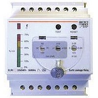
Type: ELRV-30
Earth Leakage Relay (Variable) - Type A
q
q
q
q
q
q
q
q
q
q
q
Note: The voltage
across the fault level
output MUST NOT
exceed 240V~ (For
400V~ units used in
3-Phase installations,
connect the load between
terminal 2 and neutral)
Both relays are shown
in the de-energised state
(i.e. where power is not
present on terminals 1 and 3)
* Only available on AC supply models
Fault level output*
Telephone: +44 (0) 1902 773746 Facsimile: +44 (0) 1902 420639 Email: sales@broycecontrol.com Web: http://www.broycecontrol.com
The information provided in this literature is believed to be accurate (subject to change without prior notice); however, use of such information shall be entirely at the user’s own risk.
CONNECTION DIAGRAM
FUNCTION DIAGRAM
BEFORE INSTALLATION, ISOLATE THE SUPPLY.
Connect the unit as shown in the diagram below (N.B. certain features may not be required and
therefore do not need to be connected).
Operational and setting information can be found on the reverse of this data sheet.
MOUNTING DETAILS
INSTALLATION
(i.e. lamp)
70mm DIN rail housing
Designed to monitor and detect earth fault currents (up to 30A) in conjunction with a separate toroid
Digital LED Display shows measured leakage current as well as various user settings
Microprocessor controlled with internal monitoring (self-checking)
Sensitivity (I n) and time delay ( t) adjustable using simple 2-button operation
“Display” push button allows user to view settings without needing to open the tamperproof cover
Single button operation for “Test / Reset” and connection facility for remote “Test” and “Reset” push buttons
Connection for remote lamp facility warning user prior to a trip condition (level adjustable by user)
Toroid open circuit detection forces unit to trip
2 x SPDT relay output 8A
LED indication of user settings and fault condition after unit has tripped
Positive safety
Standard
output
output
Trip level (I n)
Reset level
A1 (+ve)
A2 (-ve)
2
1
positive safety
3
4
output
5
6
7
8 10 12
Broyce Control Ltd., Pool Street, Wolverhampton, West Midlands WV2 4HN. England
t
9 11 13
standard
output
current
"reset"
fault
L3
L1
L2
14
N
E
85
45
The Earth MUST NOT pass through
the toroid.
For single phase applications, only the live
and neutral need to be passed through the
toroid.
*Cabling:
For distances >1m, use twisted pair cable between
the unit and toroid. Always ensure cables to toroid
and remote test / reset switches ARE KEPT AWAY
from mains and data cables in the same installation.
50m* max.
toroid
"test"
Installation work must be carried
interrupted
out by qualified personnel.
supply
Insert screwdriver
to release clip
failure of connection
to toroid
E
Supply voltage Un (1, 3):
Frequency range:
Isolation:
Rated impulse
(1.2 / 50 S) IEC 60664
Power consumption (max.):
Monitored leakage current:
Sensitivity I n:
Trip level limits:
Reset Value:
Time delay t:
Measured current:
Resolution:
Display accuracy:
Reset time:
Self test duration:
Memory:
Ambient temp:
Relative humidity:
Output :
Output rating:
Electrical life:
Dielectric voltage:
Rated impluse
Remote “test” / “reset”
(5, 7, 9)
Minimum trigger time:
Fault level output (1, 2):
Load (resistive):
Housing:
Weight:
Mounting option:
Terminal conductor size:
Approvals:
1. For other supply voltages, alternative trip levels or time delays, please consult the sales
2. The ELRV30 is available with a double-pole relay output:
3. Analogue outputs and communications based versions are also available; please refer to
Note: The 120 and 210mm toroids MUST NOT be used if sensitivity settings of less than
300mA are required.
( ) Numbers in brackets shown above refer to terminal numbers on the relay housing
withstand voltage:
withstand voltage:
office.
separate data sheets.
TECHNICAL SPECIFICATION
Options
Accessories
ELRV30/2/P - Output relay will de-energise on fault condition
ELRV30/2/S - Output relay will energise on fault condition
Toroids:
10- 85V DC (85 - 115% of U)
24, 115V, 230, 400V AC (85 - 115% of Un)
All AC supplies are galvanically isolated between the supply and
the toroid and remote test / reset connections.
50/60Hz (AC supplies)
Over voltage cat. III
800V (24V AC supplies ),
2.5kV (115V AC supplies)
4kV (230V, 400V AC supplies)
6VA (AC supplies) 5W (DC supplies)
0 to 30A (50/60Hz)(through external toroid with 1000:1 ratio
and connected to terminals 11 and 13)
6, 10, 30, 50, 75, 100, 300, 500, 750mA
1, 3, 5, 7.5, 10, 15, 20, 25, 30A (user selectable)
70 - 80% of I n
<7% of tripped level
inst., 50, 250, 500mS, 1, 2.5, 5, 10 sec. (user selectable)
Note: For I n settings of 30mA or less, the time delay is fixed
to inst. (instantaneous, <40mS) and is not adjustable.
0.0005 to <30A displayed on auto ranging 2 digit 7-segment
red LED display
100uA min. to 1A max.
<120mS (from supply interruption)
<5 secs. (operates at power on only)
storage of the leakage fault and reset with “test / reset” button
-5 to +60 C
-5 to +40 C (in accordance with IEC 755)
+95%
2 x SPDT relay (4, 6, 8 / 10, 12, 14)
AC1
AC15
DC1
2kV AC (rms) IEC 60947-1
4kV (1.2 / 50 S) IEC 60664
Requires two N.O. contacts. (i.e. push buttons)
>50mS
50% of I n (factory set)
User adjustable from 10 - 60% in 5% increments
40mA max. @ 240V
Note: A remote lamp can only be connected when terminals 1
and 3 are being supplied with an AC supply
Grey flame retardant Lexan UL94 VO
On to 35mm symmetric DIN rail to BS5584:1978
(EN50 002, DIN 46277-3)
Conforms to:
IEC 755. 50081-1, 50081-2, 50082-1 & 50082-2.
BZCT035 - 35mm , BZCT070 - 70mm
BZCT120 - 120mm , BZCT210 - 210mm
to DIN 43880
15% of actual measured leakage current
150,000 ops at rated load
250g
2.5mm
4mm
W. 70mm
2
and
solid
Dims:
2
stranded
250V 8A (2000VA)
250V 2.5A
25V 8A (200W)
pending. CE and
Terminal Protection to IP20
voltage when ordering.
Please state Supply
Compliant.
ELRV30-1-A
Page 1 of 2
.
Related parts for ELRV-30
Image
Part Number
Description
Manufacturer
Datasheet
Request
R

Part Number:
Description:
HOYT MODEL 17/3-19 PANEL METER RANGE AND SCALE 0-8 ADC
Manufacturer:
HOYT ELECTRICAL INSTRUMENT
Part Number:
Description:
HOYT MODEL 17/3 PANEL METER RANGE 0-50 MVDC SCALE 0-10ADC
Manufacturer:
HOYT ELECTRICAL INSTRUMENT
Part Number:
Description:
HOYT ANALOG PANEL METER RANGE 0-50 MVDC SCALE
Manufacturer:
HOYT ELECTRICAL INSTRUMENT
Part Number:
Description:
HOYT 3135 MODEL 500-0-500UADC
Manufacturer:
HOYT ELECTRICAL INSTRUMENT
Part Number:
Description:
HOYT MODEL 3136 RANGE 0-5AAC SCALE 0-25AAC
Manufacturer:
HOYT ELECTRICAL INSTRUMENT
Part Number:
Description:
HOYT ANALOG PANEL METER, RANGE 0-20DCMA SCALE 0-25 ACA
Manufacturer:
HOYT ELECTRICAL INSTRUMENT
Part Number:
Description:
HOYT ANALOG PANEL METER, RANGE 0-20MADC SCALE 0-3ACA
Manufacturer:
HOYT ELECTRICAL INSTRUMENT
Part Number:
Description:
HOYT ANALOG PANEL METER, RANGE 0-5 ACA SCALE 0-500 ACA
Manufacturer:
HOYT ELECTRICAL INSTRUMENT
Part Number:
Description:
HOYT MODEL 5036 ANALOG PANEL METER RANGE 0-5AAC SCALE 0-1000AAC
Manufacturer:
HOYT ELECTRICAL INSTRUMENT
Part Number:
Description:
HOYT MODEL 17/3-19 PANEL METER RANGE 0-50MVDC SCALE 0-8ADC
Manufacturer:
HOYT ELECTRICAL INSTRUMENT
Part Number:
Description:
HOYT MODEL 4045 ANALOG PANEL METER, ANALOG
Manufacturer:
HOYT ELECTRICAL INSTRUMENT
Part Number:
Description:
HOYT ANALOG PANEL METER RANGE AND SCALE 0-150 VAC RECTIFIED
Manufacturer:
HOYT ELECTRICAL INSTRUMENT
Part Number:
Description:
HOYT ANALOG PANEL METER RANGE
Manufacturer:
HOYT ELECTRICAL INSTRUMENT
Part Number:
Description:
HOYT ANALOG PANEL METER, MODEL 17/3 RANGE 0-1MADC SCALE 0-15KVAC
Manufacturer:
HOYT ELECTRICAL INSTRUMENT
ELRV-30 Summary of contents
Page 1
... Type: ELRV-30 Earth Leakage Relay (Variable) - Type A q 70mm DIN rail housing q Designed to monitor and detect earth fault currents (up to 30A) in conjunction with a separate toroid q Digital LED Display shows measured leakage current as well as various user settings q Microprocessor controlled with internal monitoring (self-checking) ...
Page 2
... Setting will increment automatically ("mA" and "A" yellow LED's flash simultaneously) will illuminate and the display will stop flashing. DISPLAY DISPLAY TEST/ TEST/ RESET RESET Sec SET SET DISPLAY DISPLAY TEST/ TEST/ RESET RESET Sec SET SET 4th press sec ELRV30-1-A Page ...