RM4TG20 TELEMECANIQUE, RM4TG20 Datasheet - Page 18
RM4TG20
Manufacturer Part Number
RM4TG20
Description
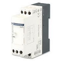
PHASE MONITORING RELAY, DPDT-2CO, 484VAC
Manufacturer
TELEMECANIQUE
Series
RM4r
Datasheet
1.RM4TG20.pdf
(30 pages)
Specifications of RM4TG20
Contact Configuration
DPCO
Phase Type
3 Phase
Supply Voltage Max
484VAC
Switching Voltage Max
440VAC
Relay Mounting
DIN Rail
Length/height, External
78mm
External Width
22.5mm
External Depth
80mm
Carry Current
8A
Available stocks
Company
Part Number
Manufacturer
Quantity
Price
Company:

Part Number:
RM4TG20
Manufacturer:
PANASONIC
Quantity:
45 000


Characteristics :
page 3/47
References :
page 3/48
Dimensions, schemes :
page 3/49
Zelio Control - measurement and control relays
3-phase supply control relays RM4-T
Presentation
Operating principle
The supply voltage to be monitored is connected to terminals L1, L2, L3 of the product.
There is no need to provide a separate power supply for RM4-T relays; they are self-powered by terminals L1, L2, L3.
i Monitoring rotational direction of phases and detection of complete failure of one of more of the phases
i Overvoltage and undervoltage detection (RM4-TR):
Function diagram (RM4-TR31, RM4-TR32)
t: time delay
Function diagram (RM4-TR33, RM4-TR34)
t: time delay
Function
Function
Function
Function
(RM4-T all models)
When terminals L1, L2, L3 are energised, the relay is energised and the yellow LED comes on if the rotational direction
of phases is correct and if all 3 phases are present.
If one or more of the phases have failed or if the rotational direction is incorrect, the relay is not energised at switch-
on. In normal operation (no fault) the relay is energised; it de-energises instantaneously in the event of failure of one
or more of the phases (any time delay set is not active on these faults).
In the event of failure or absence of a single phase, a voltage greater than the detection threshold ( 130 V on RM4-TG,
undervoltage threshold setting on RM4-TU and RM4-TR) can be generated back through the control circuit, thus
preventing detection of the phase failure. In this case, we recommend the use of RM4-TA relays.
The absence of a phase is signalled, on RM4-TR and RM4-TA, by illumination of led “P”.
In normal operation, the relay is energised and LEDs “U” and “R” are illuminated.
If the average of the 3 voltages between phases goes outside the range to be monitored, the output relay is de-
energised:
- overvoltage: the Red LED “> U” illuminates.
- undervoltage: the Red LED “< U” illuminates.
When the supply returns towards its rated value, the relay is re-energised according to the hysteresis value (5%) and
the corresponding red LED goes out.
A selector switch allows selection of an adjustable time delay from 0.1 s to 10 s. With function
“under” voltages are not taken into account. With function
re-energisation of the relay is delayed.
In all cases, in order to be detected, the duration of the overvoltage or undervoltage must be greater than the measuring
cycle time (80 ms).
TR33
242 V
230 V
208 V
198 V
0.95 x Setting > U
1.05 x Setting < U
RM4-TR31
RM4-TR32
RM4-TR33
RM4-TR34
Setting > U
Setting < U
TR34
U
15/18 25/28
15/16 25/26
15/18 25/28
15/16 25/26
U
15/18 25/28
15/16 25/26
15/18 25/28
15/16 25/26
440 V
418 V
378 V
360 V
L1 L2 L3
L1 L2 L3
(continued)
t
t
t
t
t
t
t
t
all variations above or below are taken into account and
t
t
< t
t
< t
t
< t
< t
t
t
Te
0 Volt
0 Volt
transient “over” or
3/45
3
Related parts for RM4TG20
Image
Part Number
Description
Manufacturer
Datasheet
Request
R

Part Number:
Description:
Control Contactor
Manufacturer:
TELEMECANIQUE
Datasheet:

Part Number:
Description:
Control Contactor
Manufacturer:
TELEMECANIQUE
Datasheet:

Part Number:
Description:
Contactor
Manufacturer:
TELEMECANIQUE
Datasheet:

Part Number:
Description:
Contactor
Manufacturer:
TELEMECANIQUE
Datasheet:
Part Number:
Description:
Control Contactor
Manufacturer:
TELEMECANIQUE
Datasheet:

Part Number:
Description:
CONTACTOR, 2NO/2NC, 9A, 230VAC
Manufacturer:
TELEMECANIQUE
Datasheet:

Part Number:
Description:
Contactor
Manufacturer:
TELEMECANIQUE
Datasheet:

Part Number:
Description:
CONTACTOR, 4KW, 400VAC
Manufacturer:
TELEMECANIQUE
Datasheet:

Part Number:
Description:
CONTACTOR, 5.5KW, 230VAC
Manufacturer:
TELEMECANIQUE
Datasheet:
Part Number:
Description:
CONTACTOR, 5.5KW, 400VAC
Manufacturer:
TELEMECANIQUE
Datasheet:

Part Number:
Description:
RM, RM/I, RM/ILP cores and accessories
Manufacturer:
FERROXCUBE [Ferroxcube International Holding B.V.]
Datasheet:
Part Number:
Description:
RM, RM/I, RM/ILP cores and
Manufacturer:
FERROXCUBE [Ferroxcube International Holding B.V.]
Datasheet:
Part Number:
Description:
RM Bobbins
Manufacturer:
FERYSTER [FERYSTER Inductive Components Manufacturer]
Datasheet:

Part Number:
Description:
PILOT LIGHT HEAD, WHITE
Manufacturer:
TELEMECANIQUE
Datasheet:
Part Number:
Description:
LENS HEAD, BA 9S
Manufacturer:
TELEMECANIQUE
Datasheet: