G2UM300VL20 TELE, G2UM300VL20 Datasheet - Page 2
G2UM300VL20
Manufacturer Part Number
G2UM300VL20
Description
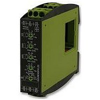
RELAY, VOLTAGE MONTR, MULTI FUN, 2 CO
Manufacturer
TELE
Series
GAMMAr
Datasheet
1.G2UM300VL20.pdf
(3 pages)
Specifications of G2UM300VL20
Contact Configuration
DPCO
Power Consumption
1W
Supply Voltage Max
240V
Relay Mounting
DIN Rail
Control Voltage Type
AC / DC
Svhc
No SVHC (18-Jun-2010)
Contact Current Ac
RoHS Compliant


Functions
When the supply voltage U is applied, the output relays switch into
on-position (yellow LED illuminated) and the set interval of the start-up
suppression (START) begins (green LED U flashes). Changes of the
measured voltage during this period do not affect the state of the output
relay. After the interval has expired the green LED is illuminated steadily.
For all the functions the LEDs MIN and MAX are flashing alternating,
when the minimum value for the measured voltage was chosen to be
greater than the maximum value.
Overvoltage monitoring (OVER, OVER+LATCH)
When the measured voltage exceeds the value adjusted at the
MAX-regulator, the set interval of the tripping delay (DELAY) begins
(red LED MAX flashes). After the interval has expired (red LED MAX
illuminated), the output relays switch into off-position (yellow LED not
illuminated). The output relays again switch into on-position (yellow LED
illuminated), when the measured voltage falls below the value adjusted
at the MIN-regulator (red LED MAX not illuminated).
If the fault latch is activated (OVER+LATCH) and the measured voltage
remains above the MAX-value longer than the set interval of the tripping
delay, the output relays remain in the off-position even if the measured
voltage falls below the value adjusted at the MIN-regulator. After
resetting the failure (interrupting and re-applying the supply voltage), the
output relays switch into on-position and a new measuring cycle begins
with the set interval of the start-up suppression (START).
Undervoltage monitoring (UNDER, UNDER+LATCH)
When the measured voltage falls below the value adjusted at the
MIN-regulator, the set interval of the tripping delay (DELAY) begins
(red LED MIN flashes). After the interval has expired (red LED MIN
illuminated), the output relays switch into off-position (yellow LED not
illuminated). The output relays again switch into on-position (yellow LED
illuminated), when the measured voltage exceeds the value adjusted
at the MAX-regulator. If the fault latch is activated (UNDER+LATCH)
and the measured voltage remains below the MIN-value longer than
the set interval of the tripping delay, the output relays remain in the off-
position even if the measured voltage exceeds the value adjusted at the
MAX-regulator. After resetting the failure (interrupting and re-applying
the supply voltage), the output relays switch into on-position and a new
measuring cycle begins with the set interval of the start-up suppression
(START).
www.tele-online.com
Window function (WIN, WIN+LATCH)
The output relays switch into on-position (yellow LED illuminated) when
the measured voltage exceeds the value adjusted at the MIN-regulator.
When the measured voltage exceeds the value adjusted at the MAX-
regulator, the set interval of the tripping delay (DELAY) begins (red LED
MAX flashes). After the interval has expired (red LED MAX illuminated),
the output relays switch into off-position (yellow LED not illuminated).
The output relays again switch into on-position (yellow LED illuminated)
when the measured voltage falls below the value adjusted at the MAX-
regulator (red LED MAX not illuminated). When the measured voltage
falls below the value adjusted at the MIN-regulator, the set interval of the
tripping delay (DELAY) begins again (red LED MIN flashes). After the
interval has expired (red LED MIN illuminated), the output relays switch
into off-position (yellow LED not illuminated).
If the fault latch is activated (WIN+LATCH) and the measured voltage
remains below the MIN-value longer than the set interval of the
tripping delay, the output relays remain in the off-position even if the
measured voltage exceeds the value adjusted at the MIN-regulator. If
the measured voltage remains above the MAX-value longer than the set
interval of the tripping delay, the output relays remain in the off-position
even if the measured voltage falls below the value adjusted at the
MAX-regulator. After resetting the failure (interrupting and re-applying
the supply voltage), the output relays switch into on-position and a new
measuring cycle begins with the set interval of the start-up suppression
(START).
G2UM300VL20
24-240V
Related parts for G2UM300VL20
Image
Part Number
Description
Manufacturer
Datasheet
Request
R

Part Number:
Description:
TELE DENSITY 39 DUAL
Manufacturer:
Tyco Electronics
Datasheet:

Part Number:
Description:
PUMP CONTROL, ALTERNATING/PARALLEL
Manufacturer:
TELE
Datasheet:

Part Number:
Description:
CURRENT MONITORING 1-PHASE
Manufacturer:
TELE
Datasheet:
Part Number:
Description:
VOLTAGE MONITORING 1 PHASE
Manufacturer:
TELE
Datasheet:

Part Number:
Description:
RELAY, VOLTAGE MONTR, 3-PHASE, 2 CO
Manufacturer:
TELE
Datasheet:

Part Number:
Description:
RELAY, VOLTAGE MONITORING, 3-PHASE
Manufacturer:
TELE
Datasheet:

Part Number:
Description:
VOLTAGE LEVEL SWITCH, 0-10VDC
Manufacturer:
TELE
Datasheet:

Part Number:
Description:
RELAY, VOLTAGE PRESET, 0-10VDC
Manufacturer:
TELE
Datasheet:

Part Number:
Description:
ASYMMETRIC FLASHER, 1 CO
Manufacturer:
TELE
Datasheet:

Part Number:
Description:
STAR-DELTA TIMER, 2 NO
Manufacturer:
TELE
Datasheet: