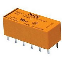
S
SPECIFICATIONS
Contacts
Coil (polarized) (at 20 C
Notes:
#1 This value can change due to the switching frequency, environmental conditions,
Remarks
* Specifications will vary with foreign standards certification ratings.
*
*
*
*
*
*
*
TYPICAL APPLICATIONS
Telecommunications equipment, data processing equipment,
facsimiles, alarm equipment, measuring equipment.
Arrangement
Initial contact resistance, max.
(By voltage drop 6 V DC 1 A)
Initial contact pressure
Contact material
Electrostatic capacitance
Thermal electromotive force
(at nominal coil voltage)
Rating
(resistive)
Expected
life (min.
operations)
Single side
stable
Latching
1
2
3
4
5
6
7
Measurement at same location as “Initial breakdown voltage” section
Detection current: 10mA
Excluding contact bounce time
Half-wave pulse of sine wave: 11ms; detection time: 10 s
Half-wave pulse of sine wave: 6ms
Detection time: 10 s
Refer to 6. Conditions for operation, transport and storage mentioned in
AMBIENT ENVIRONMENT
and desired reliability level, therefore it is recommended to check this with the
actual load.
1.102
Nominal switching capacity
Maximum switching power
Maximum switching voltage
Max. switching current
Min. switching capacity
Mechanical (at 50 cps)
Electrical
(at 20 cpm)
Minimum operating power
Nominal operating power
Minimum set and reset
Nominal set and reset
28.0
4 A 250 V AC
3 A 30 V DC
68
12.0
.472
F)
10.4
.409
#1
mm
THE VARIETY OF CONTACT
inch
4 A 250 V AC, 3 A 30 V DC
(48 VDC at less than 0.5 A)
All Rights Reserved © COPYRIGHT Matsushita Electric Works, Ltd.
Gold clad silver alloy
2 Form A 2 Form B,
3 Form A 1 Form B,
Approx. 12 g
100 A 100 m V DC
250 V AC, 30 V DC
4 A (AC), 3 A (DC)
Approx. 100 mW
Approx. 200 mW
Approx. 100 mW
Approx. 200 mW
1,000 VA, 90 W
ARRANGEMENTS
FEATURES
• The variety of contact arrangements
2 Form A 2 Form B, 3 Form A 1 Form
B, 4 Form A
• Latching types available
• High sensitivity in small size 100 mW
pick-up and 200 mW nominal
operating power
• High shock and vibration resistance
Shock: 50 G Vibration: 10 to 55 Hz at
double amplitude of 3 mm
Approx. 3 V
Approx. 3pF
4 Form A
4 A CAPACITY,
50 m
2
10
10
10
8
5
5
.42 oz
Characteristics (at 25 C
Max. operating speed
Initial insulation resistance*
Initial
breakdown
voltage*
Operate time*
(at nominal voltage)(at 20 C)
Release time (without diode)*
(at nominal voltage)(at 20 C)
Set time*
(at nominal voltage)(at 20 C)
Reset time*
(at nominal voltage)(at 20 C)
Initial contact bounce, max.
Temperature rise
(at nominal voltage)(at 20 C)
Shock resistance
Vibration resistance
Conditions for operation,
transport and storage*
(Not freezing and condens-
ing at low temperature)
Unit weight
.118 inch
2
3
(latching)
3
(latching)
Between open contacts
Between contact sets
Between contacts and
coil
3
7
Functional*
Destructive*
Functional*
Destructive
S RELAYS
• Wide switching range From 100 A
100 mV DC to 4 A 250 V AC
• Low thermal electromotive force
Approx. 3 V
• Dual-In-Line packaging arrangement
• Amber types available
1
77 F
Ambient
temp.
Humidity
3
50% Relative humidity)
4
6
5
176.4 m/s
235.2 m/s
at double amplitude of 3 mm
at double amplitude of 4 mm
Max. 35 C with nominal coil
Max. 15 ms (Approx. 8 ms)
Max. 10 ms (Approx. 5 ms)
Max. 15 ms (Approx. 8 ms)
Max. 15 ms (Approx. 8 ms)
20 cpm for maximum load,
voltage and at maximum
50 cps for low-level load
10,000 M at 500 V DC
Min. 980 m/s
Min. 490 m/s
Approx. 8 g
switching current
–40 F to +149 F
–40 C to +65 C
(1 mA 1 V DC)
5 to 85% R.H.
1,000 Vrms
1,500 Vrms
2
2
750 Vrms
{18 G}, 10 to 55 Hz
{24 G}, 10 to 55 Hz
1 ms
2
2
.28 oz
{100 G}
{50 G}