G7L-2A-T 12VDC Omron, G7L-2A-T 12VDC Datasheet - Page 14
G7L-2A-T 12VDC
Manufacturer Part Number
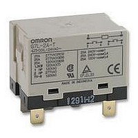
G7L-2A-T 12VDC
Description
RELAY, DPNO, 25A, 12VDC
Manufacturer
Omron
Datasheet
1.G7L-2A-T_24VDC.pdf
(14 pages)
Specifications of G7L-2A-T 12VDC
Relay Type
General Purpose
Coil Voltage Vdc Nom
12V
Contact Current Max
25A
Contact Voltage Ac Nom
220V
Coil Resistance
75ohm
Coil Type
DC Coil
Coil Current
158mA
Nom Operating Power
1.9W
Relay
RoHS Compliant
Contact Configuration
DPNO
Rohs Compliant
Yes


G7L
Precautions
Refer to page NO TAG for general precautions.
!
!
!
!
!
!
!
!
!
!
!
!
When using B-series (screw) products, the rated current from the
screw terminals (M4) should be 20 A or less according to jet stan-
dard (electrical appliance and material control law of Japan).
14
Cat. No. J055-E1-3A
Coil
Contact
Terminals
Handling
Installation
Cleaning PCB Terminals
Connecting
Rated Current Flow
To preserve performance, do not drop or otherwise subject the
Power Relay to shock.
The case is not designed to be removed during normal handling
and operation. Doing so may affect performance.
Use the Power Relay in a dry environment free from excessive
dust, SO
Do not allow a voltage greater than the maximum allowable coil
voltage to be applied continuously.
Do not use the Power Relay outside of specified voltages and
currents.
Do not allow the ambient operating temperature to exceed the
specified limit.
Although there are not specific limits on the installation site, it
should be as dry and dust-free as possible.
PCB Terminal-equipped Relays weigh approximately 100 g. Be
sure that the PCB is strong enough to support them. We
recommend dual-side through-hole PCBs to reduce solder
cracking from heat stress.
Quick-connect terminals can be connected to Faston receptacle
#250 and positive-lock connectors.
Allow suitable slack on leads when wiring, and do not subject the
terminals to excessive force.
PCB terminals have flux-tight construction which prevents flux
from penetrating into the Relay base housing, e.g., due to
capillary action up the terminals when Relay is soldered onto the
PCB. This type of Relay cannot be immersed for cleaning.
Refer to the following table when connecting a wire with a
crimp-style terminal to the G7L.
2
, H
2
S, or organic gas.
Screw terminals
ALL DIMENSIONS SHOWN ARE IN MILLIMETERS.
To convert millimeters into inches, multiply by 0.03937. To convert grams into ounces, multiply by 0.03527.
M3.5
M4
9.2
8
5.8
5.5
6.5
5
Front-connecting
M3.5
M4
Socket
9.2
8
6.5
5.3
5.5
7
!
!
Front-connecting Socket
DIN Track Mounting
!
!
!
Screw Mounting
!
!
Operating Coil
DIN Track Mounting Adapter and
As a rule, either a DC battery or a DC power supply with a
maximum of 5% ripple must be used for the operating voltage for
DC Relays. Before using a rectified AC supply, confirm that the
ripple is not greater than 5%. Ripple greater than this can lead to
variations in the operating and reset voltages.
As excessive ripple can generate pulses, the insertion of a
smoothing capacitor is recommended as shown below.
When driving a transistor, check the leakage current and
connect a bleeder resistor if necessary.
Use a DIN-conforming 50-cm track or 1-m track (both are sold
separately) for mounting a number of G7L Relays.
Cut and shorten the track to an appropriate length it if the
required track length is less than 50 cm.
The DIN Track Mounting Adapter and Front-connecting Socket
can be mounted on the G7L with just one hand and dismounted
with ease by using a screwdriver.
To support the G7L mounted on a DIN Track Mounting Adapter
or Front-connecting Socket, use the PFP-M End Plate. Put the
End Plate onto the DIN Track Mounting Adapter or
Front-connecting Socket so that the surface mark of the End
Plate faces upwards. Then tighten the screw of the End Plate
securely with a screwdriver.
Screw-mount the DIN Track Mounting Adapter or Front-connect-
ing Socket securely after opening screw mounting holes on
them.
When cutting or opening holes on the panel after the
Front-connecting Socket is mounted, take proper measures so
that the cutting chips will not fall onto the Relay terminals. When
cutting or opening holes on the upper part of the panel, mask the
Front-connecting Socket properly with a cover.
% of ripple =
E max.:
E min.:
E mean: Mean DC value
E min. E max.
Max. ripple
Min. ripple
E max. -- E min.
Smoothing
capacitor
E mean
E mean
Ripple
DC fraction
x 100
Relay
G7L
Related parts for G7L-2A-T 12VDC
Image
Part Number
Description
Manufacturer
Datasheet
Request
R

Part Number:
Description:
Relay
Manufacturer:
Omron
Datasheet:
Part Number:
Description:
Relay
Manufacturer:
Omron
Datasheet:

Part Number:
Description:
RELAY
Manufacturer:
Omron
Datasheet:
Part Number:
Description:
RELAY
Manufacturer:
Omron
Datasheet:
Part Number:
Description:
RELAY
Manufacturer:
Omron
Datasheet:

Part Number:
Description:
RELAY
Manufacturer:
Omron
Datasheet:

Part Number:
Description:
RELAY
Manufacturer:
Omron
Datasheet:
Part Number:
Description:
RELAY PWR DPST 25A 24VDC
Manufacturer:
Omron
Datasheet:
Part Number:
Description:
RELAY
Manufacturer:
Omron
Datasheet:
Part Number:
Description:
RELAY
Manufacturer:
Omron
Datasheet:

Part Number:
Description:
RELAY
Manufacturer:
Omron
Datasheet:
Part Number:
Description:
RELAY
Manufacturer:
Omron
Datasheet:

Part Number:
Description:
RELAY
Manufacturer:
Omron
Datasheet:

Part Number:
Description:
RELAY
Manufacturer:
Omron
Datasheet:
Part Number:
Description:
RELAY
Manufacturer:
Omron
Datasheet: