MY4IN 220/240ACS Omron, MY4IN 220/240ACS Datasheet
MY4IN 220/240ACS
Specifications of MY4IN 220/240ACS


Related parts for MY4IN 220/240ACS


MY4IN 220/240ACS Summary of contents
Page 1
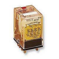
... General-purpose Relay MY New model Versatile and Function-filled Miniature Power Relay for Sequence Control and Power Switching Applications • Models with lockable test buttons now available. • Many variations possible through a selection of operation indi- cators (mechanical and LED indicators), lockable test button, built-in diode and CR (surge suppression), bifurcated contacts, etc ...
Page 2
... AC coil resistance and impedance are provided as reference values (at 60 Hz). 4. Power consumption drop was measured for the above data. When driving transistors, check leakage current and connect a bleeder resistor if required. 5. Rated voltage denoted by “*” will be manufactured upon request. Ask your OMRON representative. 2 General-purpose Relay ...
Page 3
... Max. switching 250 VAC voltage 125 VDC Max. switching 10 A current Max. switching 2,500 VA 1,250 VA power 300 W 300 W Failure rate 5 VDC (reference value) Note: Don’t exceed the carry current of a Socket in use. Please see page 10. Characteristics Item Contact resistance Operate time Release time Max ...
Page 4
Approved Standards VDE Recognitions (File No. 112467UG, IEC 255, VDE 0435) No. of poles 2 6, 12, 24, 48/50, 100/110 110/120, 200/220, 220/240 VAC 4 6, 12, 24, 48, 100/110, 125 VDC UL508 Recognitions (File No. 41515) No. of poles ...
Page 5
... Engineering Data Maximum Switching Power MY2 AC resistive load AC inductive load (cos =0.4) DC resistive load DC inductive load (L/R=7 ms) Switching voltage (V) Endurance MY2 (Resistive Loads) 10000 5000 3000 250 VAC 1000 30 VDC 500 30 VDC 300 250 VAC 100 Switching current (A) MY4 (Resistive Loads) ...
Page 6
MY4Z (Resistive Loads) 10000 5000 3000 1000 250 VAC 500 300 30 VDC 100 30 VDC 50 250 VAC 30 10 Switching Current (A) Technical and Environmental Properties Tracking Resistance Environmental Protection Flammability Class Pollution Degree Creepage Distance Clearance Distance ...
Page 7
... For AC inductive loads (such as solenoids, contactors coils, etc.) the re- duction factor corresponding to cos(p.f.) (cosine of the power factor) is multiplied by the rated current in order to identify the maximum allowable current. This approximation is not valid for loads with high inrush cur- rents such as electric motors or fluorescent lamps. ...
Page 8
Dimensions Note: All units are in millimeters unless otherwise indicated. 2-Pole Models MY2N 4-Pole Models MY4N Models with Test Button MY2IN MY4IN 8 General-purpose Relay 2.6 Eight, 1.2 dia. 2.2 long holes 0.5 28 max. 6.4 36 max. 21.5 max. ...
Page 9
Terminal Arrangement/Internal Connections (Bottom View) MY2 MY2N/MY2IN (AC Models MY2N-CR/MY2IN-CR (AC Models Only) MY4(Z) MY4(Z)N/MY4(Z)IN (AC Models MY4(Z)N-CR/MY4(Z)IN-CR ...
Page 10
Socket for MY Track-mounted (DIN Track) Socket Conforms to VDE 0106, Part 100 • Snap into position along continuous sections of any mount- ing track. • Facilitates sheet metal design by standardized mounting di- mensions. • Design with sufficient dielectric ...
Page 11
Dimensions Note: All units are in millimeters unless otherwise indicated. Socket PYF08S 23.2 max. 85 max. PYF08A-E Two, 4 mounting holes 72 max. 23 max. 22 max. PYF08A PYF-08A-N 41 ...
Page 12
Socket PYF14S 31 max. 85 max. PYF14A-E Two, 4 mounting holes 72 max. 29.5 max. PYF14A PYF-14A 29.5 max. 12 General-purpose Relay ...
Page 13
Socket PYF14-ESN 9 82 3.2 PYF14-ESS 9 83 3.2 Dimensions 27 42.5 Label Module 22 22 General-purpose Relay Terminal arrangement/ internal connections (top view)/ mounting holes ...
Page 14
Socket PY08/PY08-Y1 (See note) 42 max. Note: The PY08-Y1 includes sections indicated by dotted lines. PY08QN/ PY08QN-Y1 (See note) 42 max. Note: The PY08QN-Y1 includes sections indicated by dotted lines. PY08-02 16.5 max. PY14/PY14-Y1 (See note) 42 max. Note: The ...
Page 15
Hold-down Clips PYC-A1 (2 pcs per set) 36.3 4.5 4.5 1.2 PYC max. 3.3 38.5 Mounting Plates for Back-connecting Sockets PYP-1 Two, 3.4-dia. holes t=1.6 PYP-18 72 elliptical holes Tracks and Accessories Supporting Tracks PFP-50N/PFP-100N PYC-E1 (2 pcs ...
Page 16
... ALL DIMENSIONS SHOWN ARE IN MILLIMETERS. To convert millimeters into inches, multiply by 0.03937. To convert grams into ounces, multiply by 0.03527. Cat. No. J03E-EN-01A In the interest of product improvement, specifications are subject to change without notice. OMRON EUROPE B.V. Wegalaan 67-69, NL-2132 JD, Hoofddorp, The Netherlands Phone: +31 23 568 13 00 ...