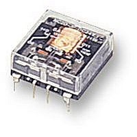
NC2D JP 24VDC PANASONIC EW, NC2D JP 24VDC Datasheet - Page 5

NC2D JP 24VDC
Manufacturer Part Number
NC2D JP 24VDC
Description
RELAY, PCB, DPCO, 24VDC
Manufacturer
PANASONIC EW
Datasheet
1.NC2D_JP_12VDC.pdf
(11 pages)
Specifications of NC2D JP 24VDC
Relay Type
General Purpose
Coil Voltage Vdc Nom
24V
Contact Current Max
5A
Contact Voltage Ac Nom
250V
Coil Resistance
1.6kohm
Coil Type
DC Coil, Monostable
Nom Operating Power
360mW
Relay Mounting
PC
Contact Configuration
DPCO
Rohs Compliant
Yes
Lead Free Status / RoHS Status
Lead free / RoHS Compliant
2C 2 coil latching
(NC2D-PL2)
4C single side stable
(NC4D-P)
4C 2 coil latching
(NC4D-PL2)
en_ds_61135_0000: 310105J
(NC2EBD-P)
(NC4EBD-P)
(NC4EBD-PL2)
9
5.08
.200
8
9
5.08
.200
5.08
.200
10
8
5.08
.200
5.08
.200
7
10
7
5.08
.200
11
7.62
.300
5.08
.200
11 12 13
5.08
.200
7
5.08
.200
7.62
.300
6
11 12 13
6 5
1.000
2.54
.100
5.08
.200
25.4
12
1.500
5
6 5
38.1
5.08
.200
5.08
.200
5.08
5.08
.200
1.500
.200
Standard type
Standard type
Standard type
38.1
5.08
.200
5.08
.200
13
4 3
4
5.08
.200
2.54
.100
5.08
.200
2.54
.100
3
4 3
5.08
5.08
5.08
.200
14
7.62
.300
14 15 16
.200
.200
5.08
.200
14 15 16
2
2
5.08
5.08
.200
2
.200
5.08
.200
5.08
.200
1
5.08
.200
1
.161
.161
4.1
1.094
1.094
4.1
27.8
27.8
.161
4.1
1.094
27.8
General tolerance: ±0.5
General tolerance: ±0.5
General tolerance: ±0.5
7.62
.300
11.2
.441
11.2
.441
7.62
7.62
.300
11.2
.441
.300
5.08
.200
5.08
.200
5.08
.200
5.08
.200
5.08
.200
5.08
.200
5.08
.200
5.08
.200
25.4
2.54
.100
±.020
±.020
5.08
.200
±.020
7.62
.300
5.08
.200
Amber sealed type
Amber sealed type
Amber sealed type
5.08
.200
5.08
.200
5.08
.200
2.54
.100
1.000
1.520
1.500
38.9
38.1
5.08
.200
5.08
.200
1.520
1.500
5.08
38.9
38.1
5.08
.200
.200
5.08
.200
2.54
.100
5.08
5.08
.200
7.62
.300
5.08
.200
2.54
.100
.200
5.08
.200
5.08
.200
5.08
.200
5.08
.200
5.08
.200
5.08
.200
5.08
.200
.161
1.094
4.1
.161
27.8
.161
4.1
1.094
4.1
27.8
1.094
27.8
11.2
.441
7.62
11.2
.441
7.62
11.2
.441
7.62
.300
.300
.300
Diagram shows the “reset” position
when terminals 3 and 6 are energized.
Energize terminals 4 and 5 to transfer
contacts.
Diagram shows the “reset” position
when terminals 3 and 6 are energized.
Energize terminals 4 and 5 to transfer
contacts.
PC board pattern (Copper-side view)
PC board pattern (Copper-side view)
PC board pattern (Copper-side view)
Schematic (Bottom view)
Schematic (Bottom view)
Schematic (Bottom view)
2.54
.100
2.54
.100
7.62
.300
7.62
.300
Deenergized position
2.54
.100
7.62
.300
9 10 11 12 13 14 15 16
9 10 11 12 13 14 15 16
9
8
9
8
2.54
.100
8
8
7
2.54
.100
2.54
.100
10
10
7
7
7
11 12 13 14
+
6
11
+
7
7
6
Tolerance: ±0.1
11
Tolerance: ±0.1
11
Tolerance: ±0.1
6
.020
+ —
+
14-1.2 DIA. HOLES
14-.047 DIA. HOLES
16-1.2 DIA. HOLES
16-.047 DIA. HOLES
0.5
5
5
+
5
.020
6
5
0.5
10-1.2 DIA. HOLES
10-.047 DIA. HOLES
12 13 14
12
12
5
5
——
4
4
4
– –
4
3
13
13
3
3 2
4
4 3
2 1
2 1
14
14
2
2
2
15 16
15 16
1
1
mm
NC
±.004
±.004
±.004
inch
5


