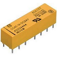
DS4E-M-DC12V PANASONIC EW, DS4E-M-DC12V Datasheet - Page 5

DS4E-M-DC12V
Manufacturer Part Number
DS4E-M-DC12V
Description
MINIATURE RELAY, 4PDT, 12VDC, 2A, THD
Manufacturer
PANASONIC EW
Datasheet
1.DS4E-M-DC12V.pdf
(6 pages)
Specifications of DS4E-M-DC12V
Contact Configuration
4PDT
Contact Current Max
2A
Contact Voltage Ac Nom
250V
Contact Voltage Dc Nom
30V
Coil Voltage Vdc Nom
12V
Coil Type
DC, Monostable
Coil Current
33.3mA
Coil Resistance
360ohm
Rohs Compliant
Yes
Lead Free Status / RoHS Status
Lead free / RoHS Compliant
Available stocks
Company
Part Number
Manufacturer
Quantity
Price
Company:
Part Number:
DS4E-M-DC12V
Manufacturer:
PANASONIC
Quantity:
2 000
Company:
Part Number:
DS4E-M-DC12V
Manufacturer:
SAARP
Quantity:
5 510
4 Form C
Single side stable, 1 coil latching, 2 coil latching
PC board pattern (Copper-side view)
Single side stable, 1 coil latching
Schematic (Bottom view)
Single side stable
Deenergized condition
REFERENCE DATA
1. Maximum switching capacity
ds_61005_0001_en_ds: 061006J
7.62
.300
.134
• A polarity bar showing the relay direction
can replace the schematic.
3.4
2.54
.100
1,000V
9.9
.340
10mV
100V
14-0.9 dia
14-.035 dia
10V
9.3
.366
N.O.
N.O.
10μA
.100 × 2
2.54 × 2
9
8
N.C.
N.C.
11
5.08
.200
6
2.54 × 2
.100 × 2
13
COM
COM
4
2.54
.100
100mA
5.08
.200
16
+
1
-
.100 × 3
2.54 × 3
COM
COM
Switching current
14
3
7.62
.300
35.24
1.387
12
N.C.
N.C.
5
.100 × 2
2.54 × 2
5.08
.200
10
1A
N.O.
N.O.
7
5.08
.200
2.54 × 2
.100 × 2
5.08
.200
2.54 × 2
.100 × 2
0.6
.024
1 coil latching
Diagram shows the “reset” position when terminals 1
and 16 are energized.
Energize with reverse polarity to transfer contacts.
2. Life curve (Resistive load)
SET
SET
5.08
.200
9
8
1,000
RST
RST
100
11
10
6
5.08
.200
0
COM
COM
13
4
5.08
.200
16
+
—
1
35.24
1.387
COM
COM
2.54
.100
14
3
5.08
.200
12
RST
RST
5
125 V DC
Switching current, A
1
10
30 V DC
SET
7
SET
5.08
.200
2 coil latching
7.62
.300
2.54
.100
5.08
.200
General tolerance: ±0.3
16-0.9 dia
16-.035 dia
2.54 × 2
.100 × 2
0.6
.024
2
2.54 × 2
.100 × 2
2.54
.100
2.54 × 2
.100 × 2
.390
7.62
.300
.221
9.9
5.6
Tolerance: ±0.1
.100
2 coil latching
Diagram shows the “reset” position when terminals 2
and 15 are energized.
Energize terminals 1 and 16 to transfer contacts.
3. Contact reliability for AC loads
Sample: DS2E-M-DC24V 10 pcs.
Cycle rate: 20 cpm.
Detection level: 200 mΩ
2.54
SET
SET
0.6
.024
±.012
2.54 × 2
.100 × 2
9
8
RST
RST
99.9
99.0
95.0
70.0
50.0
30.0
10.0
5.0
2.0
1.0
0.5
0.2
0.1
11
6
COM
COM
0
2.54 × 2
.100 × 2
13
4
15
—
+
2
16
—
+
1
±.004
2.54 × 2
.100 × 2
COM
COM
14
3
10
12
RST
RST
5
No. of operations, ×10
10
SET
7
SET
Weibull
probability data
100
4
mm
DS
1,000
inch
5


