TDRSOXB-12V Magnecraft / Schneider Electric, TDRSOXB-12V Datasheet - Page 2
TDRSOXB-12V
Manufacturer Part Number
TDRSOXB-12V
Description
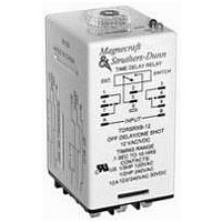
TIME DELAY RELAY, DPDT, 10H, 12VAC/DC
Manufacturer
Magnecraft / Schneider Electric
Specifications of TDRSOXB-12V
Contact Configuration
DPDT
Nom Input Voltage
12V
Delay Time Range
0.1s To 10h
Timing Adjustment
Knob
Relay Mounting
Plug In
Coil Voltage Vac Nom
12V
Contact Current Ac Max
12A
Supply Voltage
12 V
Contact Form
DPDT
Contact Rating
12 A
Termination Style
DIN Rail, Panel
Lead Free Status / RoHS Status
Lead free / RoHS Compliant


Function
A.
ON DELAY
Power On
B.
REPEAT CYCLE
Starting Off
C.
INTERVAL
Power On
D.
OFF DELAY
S Break
E.
RETRIGGERABLE
ONE SHOT
F.
REPEAT CYCLE
Starting On
G.
PULSE
GENERATOR
H.
ONE SHOT
I.
ON/OFF DELAY
S Make/Break
J.
MEMORY LATCH
S Make
M ag n e cr a f t S olu t i o n G ui de 10 5A
U = Input Voltage
FUNCTION DEFINITION TABLE
Operation
When the input voltage U is applied, timing delay t begins. Relay contacts R
change state after time delay is complete. Contacts R return to their shelf state
when input voltage U is removed. Trigger switch is not used in this function.
When input voltage U is applied, time delay t begins. When time delay t is
complete, relay contacts R change state for time delay t. This cycle will repeat
until input voltage U is removed. Trigger switch is not used in this function.
When input voltage U is applied, relay contacts R change state immediately
and timing cycle begins. When time delay is complete, contacts return to shelf
state. When input voltage U is removed, contacts will also return to their shelf
state. Trigger switch is not used in this function.
Input voltage U must be applied continuously. When trigger switch S is closed,
relay contacts R change state. When trigger switch S is opened, delay t begins.
When delay t is complete, contacts R return to their shelf state. If trigger switch
S is closed before time delay t is complete, then time is reset. When trigger
switch S is opened, the delay begins again, and relay contacts R remain in
their energized state. If input voltage U is removed, relay contacts R return to
their shelf state.
Upon application of input voltage U, the relay is ready to accept trigger signal S.
Upon application of the trigger signal S, the relay contacts R transfer and the
preset time t begins. At the end of the preset time t, the relay contacts R return to
their normal condition unless the trigger switch S is opened and closed prior to
time out t (before preset time elapses). Continuous cycling of the trigger switch S
at a rate faster than the preset time will cause the relay contacts R to remain
closed. If input voltage U is removed, relay contacts R return to their shelf state.
When input voltage U is applied, relay contacts R change state immediately
and time delay t begins. When time delay t is complete, contacts return to
their shelf state for time delay t. This cycle will repeat until input voltage U is
removed. Trigger switch is not used in this function.
Upon application of input voltage U, a single output pulse of 0.5 seconds is
delivered to relay after time delay t. Power must be removed and reapplied to
repeat pulse. Trigger switch is not used in this function.
Upon application of input voltage U, the relay is ready to accept trigger signal
S. Upon application of the trigger signal S, the relay contacts R transfer and
the preset time t begins. During time-out, the trigger signal S is ignored. The
relay resets by applying the trigger switch S when the relay is not energized.
Input voltage U must be applied continuously. When trigger switch S is closed,
time delay t begins. When time delay t is complete, relay contacts R change
state and remain transferred until trigger switch S is opened. If input voltage U
is removed, relay contacts R return to their shelf state.
Input voltage U must be applied continuously. Output changes state with every
trigger switch S closure. If input voltage U is removed, relay contacts R return to
their shelf state.
S = Trigger Switch
R = Relay Contacts
t = Time Delay
U
U
R
U
R
U
R
U
S
R
U
S
R
R
U
R
U
S
R
U
S
R
U
S
R
Timing Chart
close
open
close
open
close
open
close
open
close
open
on
off
on
off
on
off
on
off
on
off
on
off
on
off
on
off
on
off
t
t
t
t
t
t
t
t
Pulse
t
t
t
t
t
t
t
t
t
t
t
t
t
t
Pulse
t
t
t
t
t
5/3
Related parts for TDRSOXB-12V
Image
Part Number
Description
Manufacturer
Datasheet
Request
R

Part Number:
Description:
Time Delay & Timing Relays 12A DPDT BLADE
Manufacturer:
Magnecraft / Schneider Electric
Datasheet:
Part Number:
Description:
Time Delay & Timing Relays 12A DPDT BLADE
Manufacturer:
Magnecraft / Schneider Electric
Datasheet:

Part Number:
Description:
TIME DELAY RELAY, DPDT, 10H, 240VAC
Manufacturer:
Magnecraft / Schneider Electric
Datasheet:

Part Number:
Description:
Relay; E-Mech; Timing; On Delay; DPDT; Cur-Rtg 12A; Ctrl-V 120AC/DC; Blade; 8 Pin
Manufacturer:
Magnecraft/Schneider Electric
Datasheet:
Part Number:
Description:
Relay; E-Mech; Timing; On Delay; DPDT; Cur-Rtg 12A; Ctrl-V 12AC/DC; Vol-Rtg 240/30AC/DC
Manufacturer:
Magnecraft/Schneider Electric
Datasheet:
Part Number:
Description:
Relay; E-Mech; Timing; On Delay; DPDT; Cur-Rtg 12A; Ctrl-V 24AC/DC; Vol-Rtg 240/30AC/DC
Manufacturer:
Magnecraft/Schneider Electric
Datasheet:
Part Number:
Description:
Relay; E-Mech; Timing; On Delay; DPDT; Cur-Rtg 12A; Ctrl-V 120AC/DC; 8 Pin
Manufacturer:
Magnecraft/Schneider Electric
Datasheet:
Part Number:
Description:
Relay; E-Mech; Timing; On Delay; DPDT; Cur-Rtg 12A; Ctrl-V 12AC/DC; Vol-Rtg 240/30AC/DC
Manufacturer:
Magnecraft/Schneider Electric
Datasheet:
Part Number:
Description:
Relay; E-Mech; Timing; On Delay; DPDT; Cur-Rtg 12A; Ctrl-V 24AC/DC; Vol-Rtg 240/30AC/DC
Manufacturer:
Magnecraft/Schneider Electric
Datasheet:

Part Number:
Description:
Solid State Relays 3A/50VAC SPST-NO
Manufacturer:
Magnecraft / Schneider Electric
Datasheet:

Part Number:
Description:
HEAT SINK MAGNECRAFT
Manufacturer:
Magnecraft / Schneider Electric
Datasheet:
Part Number:
Description:
Bracket, Panel Mounting; Use with 711, 712, TDRSRX/SOX Series Magnecraft Relays
Manufacturer:
Magnecraft/Schneider Electric
Datasheet:
Part Number:
Description:
Bracket, DIN Rail Mounting; Use with 711, 712, TDRSRX/SOX Series Magnecraft Relays
Manufacturer:
Magnecraft/Schneider Electric
Datasheet:

Part Number:
Description:
Solid State Relays SPST-NO 48 to 480 VAC
Manufacturer:
Magnecraft / Schneider Electric
Datasheet:
Part Number:
Description:
Relay; E-Mech; Power; On Delay; SPDT; Cur-Rtg 15A; Ctrl-V 120AC; Vol-Rtg 240/24AC/DC
Manufacturer:
Magnecraft/Schneider Electric
Datasheet: