LT4HW-DC24V PANASONIC EW, LT4HW-DC24V Datasheet - Page 4
LT4HW-DC24V
Manufacturer Part Number
LT4HW-DC24V
Description
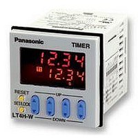
TIMER, TWIN, 11 PINS, 24VDC
Manufacturer
PANASONIC EW
Datasheet
1.LT4HW-AC240VS.pdf
(7 pages)
Specifications of LT4HW-DC24V
Contact Configuration
SPDT
Nom Input Voltage
24V
Delay Time Range
99.99s To 9999h
Adjustment Type
Pushbutton
Relay Mounting
Panel
Svhc
No SVHC (15-Dec-2010)
External Depth
65mm
External Length /
RoHS Compliant


SETTING THE OPERATION MODE, TIMER RANGE, AND TIME
Setting procedure 1) Setting the operation mode and timer range (Timer T
Setting procedure 2) Setting the time
Q Elapsed time display
W Set time display
E T
R T
T Controlled output
Y Lock indicator
U Time units display
1) Setting or changing the operational mode
(1) When the UP or DOWN key at the first digit is pressed with the set/lock switch
pressed, the mode is changed over to the setting mode.
(2) Now release the SET/LOCK key.
(3) The operational mode in the setting mode is changed over sequentially in the left or right direction by pressing the up or down key at the first digit, respectively.
(4) The operational mode displayed at present is set by pressing the RESET key, and the display returns to the normal condition.
2) Checking the operational mode
When the UP or DOWN key at the second digit is pressed with the set/lock switch pressed, the operational mode can be checked.
The display returns to the normal condition after indicating the operational mode for about two seconds. (While the display indicates the operational mode for about two
seconds, the other indicators continue to operate normally.)
3) Setting the lock
When the UP or DOWN key at the fourth digit is pressed with the set/lock switch pressed, all keys on the unit are locked.
The timer does not accept any of UP, DOWN and RESET keys.
To release the lock setting, press the UP or DOWN key at the fourth digit again with the set/lock switch pressed.
* Operational mode, adding and subtracting and minimum input signal range cannot be set at T
4) Changing over the T
The T1/T2 setting display is changed over by pressing the SET/LOCK switch. (This operation gives no effect on the other operations. The set time and elapsed time
(residual time) at T
• Changing the set time
1. It is possible to change the set time with the up and down keys even during time delay with the timer. However, be aware of the following points.
2. When the set times at T
becomes OFF.
1) If the set time is changed to less than the elapsed time with the time delay set to the addition direction, time delay will continue until the elapsed time reaches full
2) If the time delay is set to the subtraction direction, time delay will continue until “0” regardless of the new set time.
selectable indicator
indicator
1
1
scale, returns to zero, and then reaches the new set time. If the set time is changed to a time above the elapsed time, the time delay will continue until the elapsed
time reaches the new set time.
/T
/T
2
2
operation indicator
setting value
Set the operation mode and timer range with the DIP switches on the side of the unit.
DIP switches
* The 8-pin type does not have the stop input, so that the dip
Set the set time with the keys on the front of the unit.
1
Front display section
switch can be changed over between reset and signal inputs.
The signal range of the lock input is fixed (minimum 20 ms).
Pulse input
OFF-start
One operation
are linked with those at T
*4
1
2
3
5
6
7
8
1
Minimum input reset, signal, and
and T
1
/T
2
Time delay direction
setting display
2
10
11
stop signal width
3
4
5
6
are set to 0, the output becomes ON only while the signal input is carried out. However, while the reset input is carried out, the output
Time range
Time range
(Timer T
(Timer T
Pulse input
OFF-start
Repeating operation
1 2 3
Item
4 5 6 7 8
SET/LOCK
TIMER
2
RESET
.)
1
2
)
)
T1
T2
OP.
LOCK
Fourth digit
DIP switches
T1
T2
h
DOWN
UP
m
Pulse input
ON-start
Repeating operation
LT4H-W
Addition Subtraction
s
20 ms
OFF
Refer to table 1
Refer to table 2
First digit
DIP switch
1 ms
ON
02/2003
1
2
7
8
9
Integrating input
OFF-start
One operation
I UP keys
O DOWN keys
P RESET switch
{ Set/lock switch
Changes the corresponding digit of the set time in the addition direc-
tion (upwards)
Changes the corresponding digit of the set time in the subtraction
direction (downwards)
Resets the elapsed time and the output
Changes over the display between T
mode, checks the operational mode and locks the operation of each
key (such as up, down or reset key).
Ex: Setting mode display
Table 1: Setting the timer range (Timer T
Table 2: Setting the timer range (Timer T
Note: Set the DIP switches before installing the unit.
1
and T
OFF
OFF
OFF
OFF
OFF
OFF
OFF
OFF
ON
ON
ON
ON
ON
ON
ON
ON
1
6
DIP switch No.
DIP switch No.
2
1
, respectively.
/Timer T
Integrating input
OFF-start
Repeating operation
OFF
OFF
OFF
OFF
OFF
OFF
OFF
OFF
ON
ON
ON
ON
ON
ON
ON
ON
2
7
2
)
OFF
OFF
OFF
OFF
OFF
OFF
OFF
OFF
ON
ON
ON
ON
ON
ON
ON
ON
3
8
0.01 s to 99.99 s
0.1 s to 999.9 s
1 s to 9999 s
0 min 01 s to 99 min 59 s
0.1 min to 999.9 min
0 h 01 min to 99 h 59 min
0.1 h to 999.9 h
1 h to 9999 h
0.01 s to 99.99 s
0.1 s to 999.9 s
1 s to 9999 s
0 min 01 s to 99 min 59 s
0.1 min to 999.9 min
0 h 01 min to 99 h 59 min
0.1 h to 999.9 h
1 h to 9999 h
Integrating input
ON-start
Repeating operation
1
/T
Timer range
Timer range
2
settings, sets the operational
are valid after power
1
2
)
)
The new settings
OFF
LT4H-W
ON
47
Related parts for LT4HW-DC24V
Image
Part Number
Description
Manufacturer
Datasheet
Request
R

Part Number:
Description:
TIMER, TWIN, SCREW, 240VAC
Manufacturer:
PANASONIC EW
Datasheet:
Part Number:
Description:
TIMER, TWIN, 11 PINS, 240VAC
Manufacturer:
PANASONIC EW
Datasheet:
Part Number:
Description:
TIMER, TIMER, SCREW, 24VDC
Manufacturer:
PANASONIC EW
Datasheet:

Part Number:
Description:
TIMER RELAY DIG 24VDC SCREW TERM
Manufacturer:
Panasonic Electric Works
Datasheet:
Part Number:
Description:
TIMER RELAY DIGITAL 240VAC SCREW
Manufacturer:
Panasonic Electric Works
Datasheet:

Part Number:
Description:
TIMER RELAY DIGITAL 240VAC 11PIN
Manufacturer:
Panasonic Electric Works
Datasheet:
Part Number:
Description:
TIMER RELAY DIG 24VDC OCT 11PIN
Manufacturer:
Panasonic Electric Works
Datasheet:

Part Number:
Description:
Timer Multifunction
Manufacturer:
NAIS
Datasheet:

Part Number:
Description:
POWER RELAY, 24VDC, 30A, SPST-NO
Manufacturer:
PANASONIC EW
Datasheet:

Part Number:
Description:
POWER RELAY, SPDT, 12VDC, 10A, PC BOARD
Manufacturer:
PANASONIC EW

Part Number:
Description:
SIGNAL RELAY, DPDT, 5VDC, 2A, PC BOARD
Manufacturer:
PANASONIC EW
Datasheet:


Part Number:
Description:
PHOTOMOS RELAY, 60VDC, 400mA
Manufacturer:
PANASONIC EW
Datasheet:

Part Number:
Description:
PHOTOMOS RELAY, 400V, 150mA
Manufacturer:
PANASONIC EW
Datasheet: