G3VM-351A Omron, G3VM-351A Datasheet - Page 3
G3VM-351A
Manufacturer Part Number
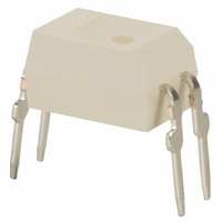
G3VM-351A
Description
SSR, MOSFET, 350V, 100mA
Manufacturer
Omron
Series
G3VMr
Datasheets
1.G3VM-2FL.pdf
(6 pages)
2.G3VM-2FL.pdf
(4 pages)
3.G3VM-351A.pdf
(4 pages)
4.G3VM-351A.pdf
(4 pages)
Specifications of G3VM-351A
Load Voltage Max
350VAC
Load Current
100mA
On State Resistance Max
50ohm
Contact Configuration
SPST-NO
Isolation Voltage
2500Vrms
Forward Current If
7.5mA
Relay Terminals
Through Hole
Height
3.65mm
Circuit
SPST-NO (1 Form A)
Output Type
AC, DC
On-state Resistance
50 Ohm
Voltage - Input
1.15VDC
Voltage - Load
0 ~ 350 V
Mounting Type
Through Hole
Termination Style
PC Pin
Package / Case
4-DIP (0.300", 7.62mm)
Control Voltage Range
1 V to 1.3 V
Load Voltage Rating
350 V
Off State Leakage Current (max)
1 uA
Load Current Rating
120 mA
Contact Form
1 Form A
Output Device
MOSFET
Mounting Style
PCB
Relay Type
MOSFET Relay
Turn-on Switching
FET
Depth
4.58mm
Rohs Compliant
Yes
Lead Free Status / RoHS Status
Lead free / RoHS Compliant
Lead Free Status / RoHS Status
Lead free / RoHS Compliant, Lead free / RoHS Compliant
Other names
G3VM351A
Z2080
Z2080
Available stocks
Company
Part Number
Manufacturer
Quantity
Price
Company:

Part Number:
G3VM-351A
Manufacturer:
HARRIS
Quantity:
6 223
Part Number:
G3VM-351A
Manufacturer:
OMRON/欧姆龙
Quantity:
20 000
Part Number:
G3VM-351AY1
Manufacturer:
OMRON/欧姆龙
Quantity:
20 000


■ Protection from Spike Voltage on the
If a spike voltage exceeding the absolute maximum rated value is
generated between the output terminals, insert a C-R snubber or
clamping diode in parallel to the load as shown in the following circuit
diagram to limit the spike voltage.
■ Unused Terminals (6-pin models only)
Terminal 3 is connected to the internal circuit. Do not connect any-
thing to terminal 3 externally.
■ Pin Strength for Automatic Mounting
In order to maintain the characteristics of the relay, the force imposed
on any pin of the relay for automatic mounting must not exceed the
following.
In direction A: 1.96 N
In direction B: 1.96 N
Guidelines for Mounting Devices on PCBs
■ Cleaning
When ions in the flux enter into the product during soldering, fluctua-
tion in device performance or corrosion may occur. Be sure to wash
away any flux residue which contains Cl or Na ions.
The following types of solvents are recommended for cleaning the
flux:
• Asahi Clean AK-225AES
• Kao Cleanthru 750H
• Pine-Alpha ST-100S
Cleaning Conditions
Cleaning conditions and precautions may vary according to product
specifications.
General precautions for dip cleaning
Dipping time varies according to the solvent used.
However, as a general guideline, it is recommended that the dip
time be limited to three minutes.
General precautions for ultrasonic cleaning
When ultrasonic cleaning is conducted for an excessively long
time, contact between the product resin and the metal leads may
lessen. Also, excessive ultrasonic stress may cause cracks in the
pellet.
It is recommended that the applied stress be minimized.
Output Terminals
Spike Voltage Protection Circuit Example
MOS FET Relays
■ Load Connection
Do not short-circuit the input and output terminals while the relay is
operating or the relay may malfunction.
Recommended conditions for standard ultrasonic cleaning
Temperature: 50°C (may vary according to the type of solvent used)
Cleaning must be conducted with the printed circuit board or device
floating on the solvent, so as to avoid direct contact between the PCB
or device and the ultrasonic vibrator.
Handling Precautions
Do not touch the device’s mark-bearing surface with your hand or
with a brush while cleaning or applying cleaning liquid to the device.
This may erase device markings. It is important to confirm that nei-
ther the solvent used for cleaning nor the cleaning conditions will
damage the device package.
Frequency:
Output:
Time:
AC Connection
DC Single Connection
DC Parallel Connection
Technical Information
+
−
+
−
+
−
+
−
27kHz to 29kHz
0.25 W/cm
30 seconds or less
1
2
3
1
2
3
1
2
3
1
2
3
2
or less
6
5
4
6
5
4
6
5
4
6
5
4
Load
Load
Load
Load
AC
Or:
+
−
−
+
+
−
DC
DC
DC
+
−
DC
Or:
−
+
DC
3
Related parts for G3VM-351A
Image
Part Number
Description
Manufacturer
Datasheet
Request
R

Part Number:
Description:
RELAY SSR SPST 120MA 6-DIP
Manufacturer:
Omron
Datasheet:

Part Number:
Description:
MOSFET SOP Relay
Manufacturer:
Omron
Datasheet:
Part Number:
Description:
MOSFET SOP Relay (Tape & Reel)
Manufacturer:
Omron
Datasheet:

Part Number:
Description:
Mosfet SSOP Relay Sample
Manufacturer:
Omron
Datasheet:
Part Number:
Description:
Mosfet SSOP Tape-N-Reel Relay
Manufacturer:
Omron
Datasheet:
Part Number:
Description:
RELAY SSR SPST 150MA 4-SOP
Manufacturer:
Omron
Datasheet:

Part Number:
Description:
RELAY SSR SPST 120MA 4-SOP
Manufacturer:
Omron
Datasheet:

Part Number:
Description:
SSR, MOSFET, 350V, 120mA
Manufacturer:
Omron
Datasheet:
Part Number:
Description:
RELAY SSR SPST 60V 400MA 4SOP
Manufacturer:
Omron
Datasheet:
Part Number:
Description:
RELAY SSR SPST 40VAC 300MA 4SOP
Manufacturer:
Omron
Datasheet:
Part Number:
Description:
Relay (Solid-State)
Manufacturer:
Omron
Datasheet:
Part Number:
Description:
Relay (Solid-State)
Manufacturer:
Omron
Datasheet:
Part Number:
Description:
MOSFET SMT Tape And Reel Relay
Manufacturer:
Omron
Datasheet:
Part Number:
Description:
MOSFET SSOP Tape&Reel - 500pcs
Manufacturer:
Omron
Datasheet:
Part Number:
Description:
MOSFET SSOP Tape & Reel-500pcs
Manufacturer:
Omron
Datasheet: