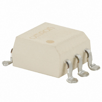
G3VM-VF Omron, G3VM-VF Datasheet - Page 82

G3VM-VF
Manufacturer Part Number
G3VM-VF
Description
SSR, MOSFET, 60V, 300mA
Manufacturer
Omron
Series
G3VMr
Datasheets
1.G3VM-2FL.pdf
(86 pages)
2.G3VM-2FL.pdf
(6 pages)
3.G3VM-2FL.pdf
(4 pages)
4.G3CN-202P1-DC3-28.pdf
(20 pages)
Specifications of G3VM-VF
Load Voltage Max
60VAC
Load Current
300mA
On State Resistance Max
2ohm
Contact Configuration
SPST-NO
Isolation Voltage
2500Vrms
Forward Current If
15mA
Relay Terminals
SMD
No. Of Pins
6
Circuit
SPST-NO (1 Form A)
Output Type
AC, DC
On-state Resistance
2 Ohm
Voltage - Input
1.15VDC
Voltage - Load
0 ~ 60 V
Mounting Type
Surface Mount
Termination Style
Gull Wing
Package / Case
6-SMD (300 mil)
Control Voltage Range
1 V to 1.3 V
Load Voltage Rating
60 V
Off State Leakage Current (max)
1 uA
Load Current Rating
300 mA
Contact Form
1 Form A
Output Device
MOSFET
Mounting Style
SMD/SMT
Relay Type
MOSFET Relay
Turn-on Switching
FET
Input Type
DC
Input Voltage (max)
1.3V
Output Voltage (max)
60V
Input Current (max)
50mA
Output Current
300mA
Circuit Arrangement
1 Form A
Package Type
SMT
Pin Count
6
Mounting
Surface Mount
Operating Temp Range
-20C to 85C
Operating Temperature Classification
Commercial
Rad Hardened
No
Lead Free Status / RoHS Status
Lead free / RoHS Compliant
Lead Free Status / RoHS Status
Lead free / RoHS Compliant, Lead free / RoHS Compliant
Other names
G3VM-VF-S
G3VMVF
G3VMVFS
Z157
G3VMVF
G3VMVFS
Z157
Available stocks
Company
Part Number
Manufacturer
Quantity
Price
Company:
Part Number:
G3VM-VF
Manufacturer:
Panasonic
Quantity:
12 000
Company:
Part Number:
G3VM-VF(TR)
Manufacturer:
RENESAS
Quantity:
1 964
Precautions
■ Reflow Solder Conditions
G3VM relays are designed to withstand a maximum soldering tem-
perature of 260°C for 10 seconds.
■ Typical Relay Driving Circuit
Use the following formula to obtain the LED current limiting resis-
tance value to assure that the Relay operates accurately.
Use the following formula to obtain the LED forward voltage value to
assure that the Relay releases accurately.
104
C-MOS
Transistor
Always turn the power off before wiring, or an electric shock may
occur.
Do not touch the SSR terminal section (the recharge section) while
the power supply is connected. Contact with the recharge section
will result in an electric shock.
Do not use excess voltage or current in the SSR input or output cir-
cuits. Otherwise, damage to the SSR or a fire will result.
Conduct wiring and soldering correctly according to soldering con-
ditions. If the product is used with incomplete wiring, overheating
will occur and may result in a fire.
Examples
WARNING
Caution
C-MOS
10 to 100 kΩ
V
V
MOS FET Relays
IN
IN
V
F (OFF)
R
1
=
+ V
V
-------------------------------------------------------
=
cc
CC
R
R
V
V
OL/OH
1
1
OL/OH
V
V
V
–
5 to 20 mA
F
F
CC
+ V
1
2
3
1
2
3
V
OL
cc
–
G3VM Series
V
–
OH
V
F
<
(ON)
0.8 V
6
5
4
6
5
4
Load
Load
■ Protection from Surge Voltage
If any reversed surge voltage is imposed on the input terminals,
insert a diode in parallel to the input terminals as shown in the follow-
ing circuit diagram and do not impose a reversed voltage value of 3 V
or more.
Spike Voltage Protection Circuit Example
■ Protection from Spike Voltage
If a spike voltage exceeding the absolute maximum rated value is
generated between the output terminals, insert a C-R snubber or
clamping diode in parallel to the load as shown in the following circuit
diagram to limit the spike voltage.
Spike Voltage Protection Circuit Example
■ Unused Terminals
Terminal 3 is connected to the internal circuit. Do not connect any-
thing to terminal 3 externally.
■ Relay Holding Force for
A Relay must not be imposed with a force exceeding 200 gf (1.96 N)
in the A or B direction shown in the following illustration when the
Relay is mounted automatically, or the characteristics of the Relay
may change.
on the Input Terminals
on the Output Terminals
Automatic Mounting
1
2
3
1
2
3
6
5
4
6
5
4
1
2
3
6
5
4


