SOM020200 CELDUC, SOM020200 Datasheet
SOM020200
Specifications of SOM020200


Related parts for SOM020200


SOM020200 Summary of contents
Page 1
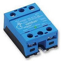
... See Instruction sheet to select the right protective components The red paths (C1/D2) must be as short as possible ! INTERNAL DIAGRAM celduc r S/CON/SOM020200/A/08/12/05 Page 1/5 UK SOM020200 Control voltage 3.5-32 range Max. permanent 110 output voltage Max. load current 20 ADC with heatsink Dimensions Weight (WxHxD) 80g ...
Page 2
... Tamb -25->+90°C Tc PROTECTION CHARACTERISTICS Ut ( Utmax : Max. nominal voltage of the relay Uto : Possible overvoltage above Utmax Utn = Ue : User DC power supply voltage S/CON/SOM020200/A/08/12/05 Page 2/5 UK VALUE 35mADC -100µA/°C typical ON=3.3V See fig. 5 1VDC typical OFF= 2.6V 32VDC -Icmax< ...
Page 3
... Power POZIDRIV2 2 N.m M5 (indicates relay has switched ON) 2 screws (M4x12mm ; tightening = 1.2N.m) STANDARD EN61000-4-2 EN61000-4-3 EN61000-4-4 EN61000-4-5 EN61000-4-11 NFEN55011 S/CON/SOM020200/A/08/12/05 Page 3/5 UK TIME CHARACTERISTICS VALUE 20µs 20µs 20µs 20µs Refer to the instruction sheet GENERAL INFORMATION Control 1.2 N.m M4 ...
Page 4
... Non-repetitive D=1% (Tc=100°C, Tjmax=175°C) 160 140 Repetitive D=5% (Tc=100°C, Tjmax=175°C) 120 Repetitive D=10% (Tc=100°C, Tjmax=175°C) 100 Repetitive D=50% (Tc=100°C, Tjmax=125° 0,1 1 S/CON/SOM020200/A/08/12/05 CHARACTERISTIC CURVES ON RESISTANCE VS JUNCTION TEMPERATURE 120 100 - Junction Temperature (°C) 1.1K/W 0,9K/W 0 ...
Page 5
... PRELIMINARY DATA Fig. 9 Fig. 10 Rue Ampère B.P. 4 Phone : 33 ( Fax : 33 ( Email : celduc-relais@celduc.com DIMENSIONS AND ACCESSORIES DIMENSIONS (mm ACCESSORIES FASTON : Please contact us celduc ® 42290 SORBIERS - France S/CON/SOM020200/A/08/12/05 Page 5/5 UK www.celduc.com ...