SOM040200 CELDUC, SOM040200 Datasheet - Page 2
SOM040200
Manufacturer Part Number
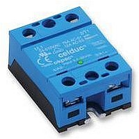
SOM040200
Description
RELAY. 40A/12-120V/3.5-32V
Manufacturer
CELDUC
Datasheet
1.SOM040200.pdf
(5 pages)
Specifications of SOM040200
Load Voltage Max
110VDC
Load Current
40A
On State Resistance Max
46mohm
Isolation Voltage
2.5kV
Forward Current If
35mA
Svhc
No SVHC (18-Jun-2010)
Control Voltage Type
DC
Load Current Rms Max
40A
Relay Terminals
Screw
Rohs Compliant
Yes
Control Voltage Dc Max
32V
Control Voltage Dc Min
3.5V
Lead Free Status / RoHS Status
Lead free / RoHS Compliant


Nom. Control voltage
Min. Control current
Control voltage range
Control current consumption
Releasing control voltage
Max. reverse control voltage
Input impedance
Nominal voltage
Voltage range
Non-repetitive peak voltage
Overvoltage protection
Max reverse voltage drop
(internal diode at OFF state)
Maximum nominal currents
Non-repetitive peak overload
current
Min. load current
Max. leakage current
Max. on-state resistance
Typ. output capacitance
Junction/case thermal
resistance per power element
Built-in heatsink thermal
resistance vertically mounted
Heatsink thermal time constant
Control inputs/power outputs
insulation voltage
Inputs/case insulation voltage
Outputs/case insulation voltage
Isolation resistance
Isolation capacitance
Maximum junction temperature
Storage ambient temperature
Operating ambient temperature
Max. case temperature
Ielk : Leakage current of the relay
Ie : User load nominal current
Utp : Relay max. non repetitive peak voltage
celduc
r
Ielk / Ie
0,8
0,6
0,4
0,2
1
0
Leakage current (Ielk) vs DC voltage (Ut)
e
0
l
CHARACTERISTIC
CHARACTERISTIC
a
20 40
i
s
®
60 80 100 120 140 160 180 200
( =U emax)
U t max
PRELIMINARY DATA
Ucoffmax
Ut
Ielk max
-Ucmax
LABEL
Ucnom
LABEL
Uenom
Id max
RDSon
Ie max
Tjmax
Rthra
Icmin
Iemin
Tthra
Tamb
Rthjc
Uimp
Uimp
Uimp
Cout
Tstg
Utp
U t p
Rin
Rio
Cio
-Ut
Uc
D1
Tc
Ic
Ut (V)
Ue
Utmax : Max. nominal voltage of the relay
Uto : Possible overvoltage above Utmax
Utn = Ue : User DC power supply voltage
CONTROL INPUT CHARACTERISTICS
Resistive
32 – 35mADC (for control voltage range)
POWER OUTPUT CHARACTERISTICS
40A
PROTECTION CHARACTERISTICS
Varistor 75V size 20
Current limitation
3.5 – 32VDC
-40->+100°C
-25->+90°C
10 minutes
5-110VDC
12-24VDC
35mADC
VALUE
VALUE
90VDC
0.7K/W
32VDC
10K/W
1VDC
46mΩ
175°C
100°C
1.1nF
2.5kV
2.5kV
2.5kV
200V
380A
<8pF
1.5V
5mA
3mA
1GΩ
Absolute limits
S/CON/SOM040200/A/08/12/05
Please contact us
t : Overvoltage duration
T: Time between 2 overvoltage
Motor
⇒
t
max
(
Uto
P
=
(
protection
−
(
Uto <
Uto
Ut
max)
T
−
)
Utp
=
Ut
Page 2/5 UK
0
1
.
W
-Icmax<100µA
@Utmax @Tjmax
@∆Tra=75°C
@∆Tra=40°C
75
@Iemax @Tjmax
max)
×
typical OFF= 2.6V
typical ON=3.3V
-100µA/°C
See fig. 5
See fig. 5
See fig. 7
See fig. 8
See fig. 7
@Ie=-56A
(limits)
Ie
max
INFO.
INFO.
@Uc=0
×
×
t
Ie
≤
1
Related parts for SOM040200
Image
Part Number
Description
Manufacturer
Datasheet
Request
R

Part Number:
Description:
EXTERNAL SWITCH CONTROLED SINGLE PHASE SOLID STATE RELAYS
Manufacturer:
CELDUC [celduc-relais]
Datasheet:

Part Number:
Description:
REED SWITCH DRY CONTACT CHANGEOVER
Manufacturer:
CELDUC [celduc-relais]
Datasheet:
Part Number:
Description:
DC Solid State Relay
Manufacturer:
CELDUC [celduc-relais]
Datasheet:
Part Number:
Description:
Support Interfaces E/S DIN rail adaptor for I/O modules
Manufacturer:
CELDUC [celduc-relais]
Datasheet:
Part Number:
Description:
DC SOLID STATE RELAY
Manufacturer:
CELDUC [celduc-relais]
Datasheet:
Part Number:
Description:
AC BLINKING SSR
Manufacturer:
CELDUC [celduc-relais]
Datasheet:
Part Number:
Description:
RELAY WITH PROPORTIONAL CONTROL
Manufacturer:
CELDUC [celduc-relais]
Datasheet:
Part Number:
Description:
Double Solid State Relay
Manufacturer:
CELDUC [celduc-relais]
Datasheet:
Part Number:
Description:
MOSFET BASED DC SOLID-STATE RELAY
Manufacturer:
CELDUC [celduc-relais]
Datasheet:
Part Number:
Description:
REED SWITCH NORMALY OPEN, DRY CONTACT
Manufacturer:
CELDUC [celduc-relais]
Datasheet:
Part Number:
Description:
AC SOLID STATE INPUT MODULE
Manufacturer:
CELDUC [celduc-relais]
Datasheet:
Part Number:
Description:
DC SOLID STATE INPUT MODULE
Manufacturer:
CELDUC [celduc-relais]
Datasheet:
Part Number:
Description:
SLIM SOCKET
Manufacturer:
CELDUC [celduc-relais]
Datasheet:
Part Number:
Description:
HIGH VOLTAGE REED SWITCH NORMALY OPEN, DRY CONTACT
Manufacturer:
CELDUC [celduc-relais]
Datasheet: