SOM40100 CELDUC, SOM40100 Datasheet

RELAY. 40A/12-60V/3.5-32V

SOM40100

Manufacturer Part Number
SOM40100
Description
RELAY. 40A/12-60V/3.5-32V
Manufacturer
CELDUC
Datasheet

Specifications of SOM40100

Load Voltage Max
60VDC
Load Current
40A
On State Resistance Max
30mohm
Isolation Voltage
2.5kV
Forward Current If
35mA
Svhc
No SVHC (18-Jun-2010)
Control Voltage Type
DC
Load Current Rms Max
40A
Relay Terminals
Screw
Rohs Compliant
Yes
Control Voltage Dc Max
32V
Control Voltage Dc Min
3.5V
Lead Free Status / RoHS Status
Lead free / RoHS Compliant
Proud to serve you
Proud to serve you
Proud to serve you
Proud to serve you
Data given at Tambient=25°C and subject to modification without previous notice
Fig. 1
Fig. 3
Load voltage
Latest MOSFET technology generation.
Ultra low on-state resistance.
Low output leakage current.
Low control current consumption.
Built-in overvoltage protection
Reverse protected triggered control input to avoid linear control
risks
No radiated or conducted disturbances
Touch protected housing IP20
5-60VDC
range
celduc
r
e
l
a
i
HIGH SIDE WIRING DIAGRAM
s
®
Load current
(with heatsink)
Up to 40A
(Load connected to “-“)
range
DC SOLID-STATE RELAY
Control input
voltage range
3.5-32VDC
MOSFET BASED
PRELIMINARY DATA
sheet to select the
(C1/D2) must be
right protective
The red paths
See Instruction
components
as short as
possible !
INTERNAL DIAGRAM
In & case / Out
Insulation
2.5kV
Fig. 2
celduc
r
Screw terminals
Connections
e
LOW SIDE WIRING DIAGRAM
(Load connected to “+”)
Control voltage
range
Max. permanent
output voltage
Max. load current
with heatsink
l
S/CON/SOM040100/A/08/12/05
45 x 58.5 x 30
Dimensions
(WxHxD)
SOM040100
a
i
Page 1/5 UK
See Instruction
paths (C1/D2)
3.5-32
sheet to select
components
must be as
possible !
protective
Weight
60
40
the right
short as
The red
80g
VDC
ADC
s
VDC
®

Related parts for SOM40100

SOM40100 Summary of contents

Page 1

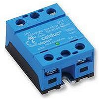
... Insulation 3.5-32VDC 2.5kV Screw terminals Fig. 2 See Instruction sheet to select the right protective components The red paths (C1/D2) must be as short as possible ! INTERNAL DIAGRAM celduc r S/CON/SOM040100/A/08/12/05 Page 1/5 UK SOM040100 Control voltage 3.5-32 range Max. permanent 60 VDC output voltage Max. load current 40 ...

Page 2

... PRELIMINARY DATA CHARACTERISTIC Nom. Control voltage Min. Control current Control voltage range Control current consumption Releasing control voltage Max. reverse control voltage Input impedance CHARACTERISTIC Nominal voltage Voltage range Non-repetitive peak voltage Overvoltage protection Max reverse voltage drop (internal diode at OFF state) ...

Page 3

... PRELIMINARY DATA Fig. 4 CHARACTERISTIC Turn on time Turn on delay Turn off time Turn off delay Max. On-Off frequency Connections Screwdriver advised Min and max tightening torque Insulated crimp terminals (round tabs, eyelet type) Display Housing Mounting Noise level Weight Standards ...

Page 4

... PRELIMINARY DATA Fig. 5 INPUT CHARACTERISTIC Ic (mADC Fig. 7 POWER DISSIPATED AND LOAD CURRENT LIMIT VS TEMPERATURE Permanent current Ie (ARMS 4K/W 10K 10K Heatsink 4K/W = 150x150x3mm aluminium sheet 2.1K/W = WF210000 1.2K/W = WF121000 0.75K/W = WF070000 0.55K/W = WF050000 Fig. 8 PEAK OVERLOAD CURRENT vs. PULSE DURATION CHARACTERISTIC ...

Page 5

... PRELIMINARY DATA Fig. 9 Fig. 10 Rue Ampère B.P. 4 Phone : 33 ( Fax : 33 ( Email : celduc-relais@celduc.com DIMENSIONS AND ACCESSORIES DIMENSIONS (mm ACCESSORIES FASTON : Please contact us celduc ® 42290 SORBIERS - France S/CON/SOM040100/A/08/12/05 Page 5/5 UK www.celduc.com ...

Related keywords