W6440ASX-1 Magnecraft / Schneider Electric, W6440ASX-1 Datasheet - Page 8
W6440ASX-1
Manufacturer Part Number
W6440ASX-1
Description
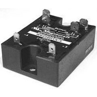
SSR, PANEL MOUNT, 480VAC, 280VAC, 40A
Manufacturer
Magnecraft / Schneider Electric
Datasheet
1.6210AXXSZS-AC90.pdf
(28 pages)
Specifications of W6440ASX-1
Control Voltage Range
90VAC To 280VAC
Operating Voltage Range
48VAC To 480VAC
Load Current
40A
Isolation Voltage
4000VAC
Control Voltage Type
AC
Relay Terminals
Screw
Lead Free Status / RoHS Status
Lead free / RoHS Compliant


2...
7
PROTECTING THE OUTPUT SWITCH:
An SCR is a four layer semiconductor having 3 terminals:
Cathode, anode and Gate. Normally it blocks current in
both the forward and reverse directions. The SCR is
triggered on in the forward direction by a small gate
current. The SCR remains on until load current decreases
to a value less than necessary to maintain the SCR in
the on state. When switching AC, two SCRS are
connected in inverse parallel.
A Triac also has 3 terminals, like the SCR, it normally
blocks current in both directions; but may be triggered
in either direction by a small gate current
Both SCR's and Triacs are members of the thyristor
family. Therefore, we use this term to denote both devices.
There are 4 ways to put a thyristor into a conducting
mode. Only one method is desirable and the other
three are the source of most application problems.
The 4 methods of Thyristor turn-on are -
A. Gate Turn-on: By injecting a controlled current
B. Forward Breakover Turn-on: A voltage in excess
C. DV/DT turn-on: A voltage which rises faster than
D. Thermal Turn-on: Allowing the temperature of the
SOLID STATE RELAY SELECTION CHART
APPLICA
APPLICA
90 - 280VAC
CONTROL
thyristor to go beyond the value sufficient to
cause excessive leakage current, causing turn-on
and possible thermal runaway.
VOLTAGE
3 - 30VDC
of the Breakover (or Peak Blocking) voltage across
into the gate (the desired method).
thyristor.
the Thyristor can tolerate, and still remain in the
off state.
5 or 12 VDC
VOLTAGE
240 VAC
200 VDC
600 VAC
480 VAC
600 VAC
60 VDC
LOAD
or
PC/PUSH ON TERM.
PC BOARD (SIP)
TION DA
MOUNTING
TION DA
PC BOARD
DIN/PANEL
SOCKET
PANEL
PANEL
PANEL
H PACK
L PACK
F PACK
V PACK
K PACK
M PACK
N PACK
S PACK
W6 series (DDX
W6 series (DSX)
W6 series (DTX)
SSR-DIN-DC
SSR-DIN-AC
W6 series (ASX)
W226
T
T
A
A
2
3
4
The last three methods can be protected against as
follows. In those situations where high peak voltage
transients occur, effective protection can be obtained by
using metal oxide varistors (MOV). The MOV is a
bidirectional voltage sensitive device that has low
impedance when its design voltage threshold is exceeded.
HEAT SINKING:
It is important to select the right size heat sink for your
applications. SSR's will typically generate 1.2 watts per
amp of load current. The total wattage times the thermal
resistance equal the temperature. For example a 25 amps
SSR with a 20 amps load applied dissipates 24 watts
when mounted on a aluminum plate 6" X 6" X 1/8" with
aluminum plate. 20 amps x 1.2 watts / amp = 24 watts.
24 watts x 1˚C / watts = 24˚C rise.
FUSING:
The SSR has a I
amount of energy it can safely handle without damage.
The
energy the fuse will pass to the SSR. To protect the SSR,
an inline fuse rating should be less than that of the SSR.
rating will normally fail as a shorted unit.
EXPRESSIONS USED IN SPECIFICATIONS
5
An SSR exposed to a surge greater than its non-repetitive
thermal grease applied between the SSR base and
LOAD CURRENT AMPS
dv
dt
V =
PF=
R
I =
F =
L =
C =
6
1
I
& R
2
10
T rating of the fuse is a measure of the amount of
2
=
12
Equals the maximum permissable
rate of change of voltage in
volts/microseconds
Line Voltage
Load Current
Load Power Factor
Line Frequency
Inductance in Henrys
Capacitance in Microfarads
Resistance in Ohms
25
2
T rating which is a measure of the
40
50
75
SOLID STATE RELAYS
90
125
21 - 22
21 - 22
19 - 20
23 - 24
19 - 20
17 - 18
17 - 18
13 - 14
PAGE
16
12
11
10
25
8
8
Related parts for W6440ASX-1
Image
Part Number
Description
Manufacturer
Datasheet
Request
R

Part Number:
Description:
Solid State Relays 3A/50VAC SPST-NO
Manufacturer:
Magnecraft / Schneider Electric
Datasheet:

Part Number:
Description:
HEAT SINK MAGNECRAFT
Manufacturer:
Magnecraft / Schneider Electric
Datasheet:

Part Number:
Description:
Bracket, Panel Mounting; Use with 711, 712, TDRSRX/SOX Series Magnecraft Relays
Manufacturer:
Magnecraft/Schneider Electric
Datasheet:
Part Number:
Description:
Bracket, DIN Rail Mounting; Use with 711, 712, TDRSRX/SOX Series Magnecraft Relays
Manufacturer:
Magnecraft/Schneider Electric
Datasheet:

Part Number:
Description:
Solid State Relays SPST-NO 48 to 480 VAC
Manufacturer:
Magnecraft / Schneider Electric
Datasheet:
Part Number:
Description:
Solid State Relays SPST-NO 48 to 480 VAC
Manufacturer:
Magnecraft / Schneider Electric
Datasheet:
Part Number:
Description:
Solid State Relays SPST-NO 3 to 50 VDC
Manufacturer:
Magnecraft / Schneider Electric
Datasheet:
Part Number:
Description:
Solid State Relays SPST-NO 48 to 600 VAC
Manufacturer:
Magnecraft / Schneider Electric
Datasheet:
Part Number:
Description:
Solid State Relays SPST-NO 3 to 150 VDC
Manufacturer:
Magnecraft / Schneider Electric
Datasheet:
Part Number:
Description:
Solid State Relays SPST-NO 48 to 600 VAC
Manufacturer:
Magnecraft / Schneider Electric
Datasheet:
Part Number:
Description:
Solid State Relays SPST-NO 24 to 280 VAC
Manufacturer:
Magnecraft / Schneider Electric
Datasheet:

Part Number:
Description:
Solid State Relays 5V/240V PC TERMINAL
Manufacturer:
Magnecraft / Schneider Electric

Part Number:
Description:
Solid State Relays SPST-NO 8 A 3.5-32 VDC
Manufacturer:
Magnecraft / Schneider Electric
Datasheet:
Part Number:
Description:
Solid State Relays SPST-NO 24 to 280 VAC
Manufacturer:
Magnecraft / Schneider Electric
Datasheet:
Part Number:
Description:
Relay; E-Mech; Power; On Delay; SPDT; Cur-Rtg 15A; Ctrl-V 120AC; Vol-Rtg 240/24AC/DC
Manufacturer:
Magnecraft/Schneider Electric
Datasheet: