PM1205 Clare, PM1205 Datasheet - Page 2
PM1205
Manufacturer Part Number
PM1205
Description
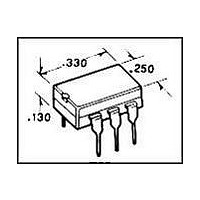
SSR, PCB MOUNT, 240VAC, 1.4V, 500mA
Manufacturer
Clare
Specifications of PM1205
Control Voltage Type
DC
Input Voltage
0.9V To 1.4V
Contact Configuration
SPST-NO
Load Current
500mA
Load Voltage Range
20Vrms To 240Vrms
Switching Mode
AC Switch
Relay Terminals
Through Hole
Lead Free Status / RoHS Status
Lead free / RoHS Compliant
Lead Free Status / RoHS Status
Lead free / RoHS Compliant
Available stocks
Company
Part Number
Manufacturer
Quantity
Price

Company:
Part Number:
PM1205
Manufacturer:
VISHAY
Quantity:
5 510


1
2
Absolute Maximum Ratings @ 25ºC
1
2
Electrical Characteristics @ 25ºC
2
Parameter
Output Characteristics
AC Operating Voltage
Load Current (Continuous)
Maximum Surge Current
Off-State Leakage Current
On-State Voltage Drop
Critical Rate of Rise
Switching Speeds
Zero-Cross Turn-On Voltage
Operating Frequency
Load Power Factor for Guaranteed Turn-On
Capacitance Input-To-Output
Input Characteristics
Input Control Current
Input Voltage Drop
Input Dropout Voltage
Reverse Input Current
Parameter
Blocking Voltage
Reverse Input Voltage
Input Control Current
Input Power Dissipation
Total Package Dissipation
Isolation Voltage, Input to Output
Operational Temperature
Storage Temperature
Turn-On
Turn-Off
Derate Linearly 1.33 mW / ºC
Derate Linearly 6.67 mW / ºC
For Normal Environment
For High Noise Environment
Zero Cross 1
Snubber circuits may be required at low power factors.
Peak (10ms)
st
half-cycle @ < 100Hz.
1
1
2
3750
Min
-40
-40
-
-
-
-
-
-
2
Max
+125
500
100
150
800
+85
5
1
Subsequent half-cycle
-
V
Conditions
L
1
=120-240VAC
V
I
st
L
L
I
t<16ms
I
I
=0.5A
V
F
=500V
F
half-cycle
F
=5mA
=5mA
=5mA
Units
R
=5V
mW
mW
V
-
-
-
-
-
-
-
mA
V
ºC
ºC
V
A
rms
www.clare.com
P
rms
DC
Symbol
Absolute Maximum Ratings are stress ratings. Stresses in
excess of these ratings can cause permanent damage to
the device. Functional operation of the device at conditions
beyond those indicated in the operational sections of this
data sheet is not implied.
dV/dt
I
I
V
PEAK
C
LEAK
PF
V
t
t
I
I
I
on
off
OP
-
-
-
-
L
I/O
F
R
F
0.005
Min
1000
0.25
0.9
0.8
20
20
-
-
-
-
-
-
-
-
-
-
-
1200
Typ
1.2
2
3
-
-
-
-
-
-
-
-
-
-
-
-
-
-
Max
240
500
0.5
1.4
0.5
0.5
1.4
12
10
10
1
5
1
5
-
-
-
-
PM1205
Units
Cycles
V/µs
V
A
V
mA
mA
Hz
pF
µA
A
V
V
V
V
rms
rms
rms
-
R08
Related parts for PM1205
Image
Part Number
Description
Manufacturer
Datasheet
Request
R

Part Number:
Description:
Clare Solar Cells
Manufacturer:
Clare, Inc.
Datasheet:
Part Number:
Description:
Clare Solar Cells
Manufacturer:
Clare, Inc.
Datasheet:
Part Number:
Description:
4 Pin SOP OptoMOS Relay
Manufacturer:
CLARE [Clare, Inc.]
Datasheet:

Part Number:
Description:
MOSFET N-CH 350V 5MA SOT-223
Manufacturer:
Clare
Datasheet:
Part Number:
Description:
MOSFET N-CH 350V 5MA SOT-223
Manufacturer:
Clare
Datasheet:

Part Number:
Description:
IC DRVR PROGRAMMABLE 16-SOIC
Manufacturer:
Clare
Datasheet:

Part Number:
Description:
IC PHONE LINE MONITOR 8-SOIC
Manufacturer:
Clare
Datasheet:

Part Number:
Description:
IC LITELINK III FULL RING 32SOIC
Manufacturer:
Clare
Datasheet:

Part Number:
Description:
LITELINK III PHONE LINE 32SOIC
Manufacturer:
Clare
Datasheet:

Part Number:
Description:
RELAY OPTO TELCOM 12OMA 8-DIP
Manufacturer:
Clare
Datasheet:
Part Number:
Description:
IC PHONE LINE MONITOR 8-SOIC
Manufacturer:
Clare
Datasheet:
Part Number:
Description:
RELAY OPTOMULTLIFUN 100MA 8FLTPK
Manufacturer:
Clare
Datasheet: