LH1541AT1 Vishay, LH1541AT1 Datasheet
LH1541AT1
Specifications of LH1541AT1


Related parts for LH1541AT1

LH1541AT1 Summary of contents
Page 1
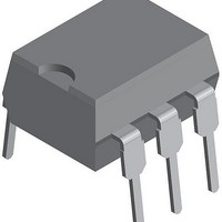
... Part Identification Part Number Description LH1541AT1 6-pin DIP, Tubes LH1541AAB1 6-pin SMD, Gullwing, Tubes LH1541AAB1TR 6-pin SMD, Gullwing, Tape and Reel 1 Form A Solid State Relay (Low Capacitance ...
Page 2
... I F Ω 110 160 I =5.0 mA — — =5.0 mA Ω 10000 — mA 0.4 200 mA µ A — 4.8 — mA — mA 0.15 — =5 0.8 — ISO 0.12 0. =5.0 mA 0.3 0.25 ms =5.0 mA RMS = =100 mA L =±100 V L =±100 V L =±200 =1 www.vishay.com 3–160 ...
Page 3
... SEE ELEC. CHAR Figure 6. Switch Capacitance vs. Applied Voltage I = 100 mA L TYP 160 150 120 –30 –60 –40 – Ambient Temperature (° –10 –20 –30 –40 –40 – Ambient Temperature (°C) 6.0 5.0 4.0 3.0 2.0 1.0 0 Applied Voltage ( 100 www.vishay.com 3–161 ...
Page 4
... Figure 12. Switch Breakdown Voltage vs. Temperature 3 5 3.0 2.5 2.0 1.5 1.0 0 Ambient Temperature (°C) 85°C 70° 50° 100 120 Load Voltage ( –2 –4 –6 –8 –10 –40 – Ambient Temperature (° 140 160 180 200 60 80 www.vishay.com 3–162 ...
Page 5
... Ambient Temperature (°C) Document Number: 83834 Revision 17-August-01 Figure 16. Turn-on Time vs. LED Current 1.50 1.25 1.00 0.75 0.50 0. Figure 17. Turn-off Time vs. LED Current +85°C +25°C –40° LED Forward Current (mA) –40°C +85°C +25° LED Forward Current (mA www.vishay.com 3–163 ...
Page 6
This datasheet has been download from: www.datasheetcatalog.com Datasheets for electronics components. ...