92-458.700 EAO, 92-458.700 Datasheet - Page 8
92-458.700
Manufacturer Part Number
92-458.700
Description
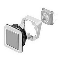
ACTUATOR 5N, 92 SERIES PUSHBUTTON SWITCH
Manufacturer
EAO
Datasheet
1.92-458.700.pdf
(26 pages)
Specifications of 92-458.700
Operating Force Max
5N
Mounting Hole Dia
16mm
Actuator Diameter
18.4mm
Contact Current Max
50mA
Leaded Process Compatible
Yes
Actuator Style
Square
Rohs Compliant
Yes
For Use With
92 Series Illuminated Pushbutton Switches
Lead Free Status / RoHS Status
Lead free / RoHS Compliant


Mounting instruction
0
The arrangement of the mounting flanges and their number is determined by the size of
the front panel or PCB. To ensure uniform, tactile switching, we recommend a layout of
the flanges as per adjacent sketch.
For large PCBs with several switching elements we recommend the following procedure :
1. Fit the actuator to the front panel.
2. Clip the mounting flange to the rear of the intended actuator.
3. Screw the PCB with the components soldered to it to the assembled mounting flange.
This arrangement applies to PCBs 1.6 mm thick.
>
0
The tool 92-971.0 must be used for removing the mounting flange from the actuator. Before
removing the flange, the PCB fixing screws must be loosened.
If the number of actuators is insufficient, use the spacer 92-965.0 which can be attached
to the front panel.
The spacer can be adjusted to the following front panel thicknesses: 1.5/2/2.2/3/3.5/4 mm
and can be stuck to the back of the panel free of dirt and grease.
Arrangement mounting flange
Dismantling mounting flange
6
06.2010
60 max.
Front plate
PCB
Spacer
92
Related parts for 92-458.700
Image
Part Number
Description
Manufacturer
Datasheet
Request
R


Part Number:
Description:
Indicator
Manufacturer:
EAO
Datasheet:


Part Number:
Description:
Switch Actuator
Manufacturer:
EAO
Datasheet:

Part Number:
Description:
Switch Actuator
Manufacturer:
EAO
Datasheet:
Part Number:
Description:
Switch Actuator
Manufacturer:
EAO
Datasheet:


Part Number:
Description:
SINGLE CHIP LED/ T1 BI-PIN/ 2.1VDC/20MA - RED
Manufacturer:
EAO
Datasheet:

Part Number:
Description:
INDICATOR, INCAND LAMP, BI PIN
Manufacturer:
EAO
Datasheet:

Part Number:
Description:
INDICATOR, BI-PIN
Manufacturer:
EAO
Datasheet:

Part Number:
Description:
INDICATOR, INCAND LAMP, MIDGET GROOVED
Manufacturer:
EAO
Datasheet: