704-6003 EAO, 704-6003 Datasheet
704-6003
Specifications of 704-6003


Related parts for 704-6003


704-6003 Summary of contents
Page 1
...
Page 2
... Switches and Indicators 04 ...
Page 3
... Mounting Instruction Product Range Technical Data Technical Drawing / Dimension / Diagrams Circuit Drawing Typical Applications Marking 66 01.2002 - pushbuttons for standard mounting - pushbuttons for flush mounting - accessories / spare parts Page 67 Page 68 Page 71 Page 72 Page 89 Page 99 Page 118 Page 122 Page 131 Page 142 ...
Page 4
... Keylock switch Standard lock No. = 251 with ending of part No. 0 (example 704.335.0). Following lock No. also available (lock No./ending of part No.) 252/1, 253/2, 254/3, 255/4, 256/5, 257/6, 259/8, 260/9. 2 keys will be delivered per keylock switch. All dimensions in mm. ...
Page 5
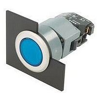
product assembly illuminated pushbutton for flush mounting 0 illuminated pushbutton 0 rotary switch for flush mounting 0 68 01.2002 1 front bezel set for flush mounting 2 lens 3 marking plate 4 actuator housing 5 front plate 6 pressure ring ...
Page 6
product assembly rotary switch 0 1 rotary switch actuator 2 mounting flange 3 rotary switch element 04 69 01.2002 ...
Page 7
... The switch is fixed and positioned by evenly tightening the two screws in the mounting flange to a max torque of 25 Ncm. A re- ducing ring can be used to fit 22.5 mm switches into a 30.5 mm hole. The switching elements (max transformers can easily be snapped in position without tools ...
Page 8
Mounting Instruction Rotary switch Actuator Mounting instructions, installation in Ø 22.5 mm hole Step 1 Mounting the actuator element 1. Insert actuator from the front into the mounting hole Ø 22.5 mm. 2. Push mounting flange onto the actuator from ...
Page 9
... Typ-Nr. 704.021 0,020 704.021 0,020 704.021 0,020 704.021 0,020 704.021 0,020 704.020 0,020 704.020 0,020 704.020 0,020 704.020 0,020 704.020 0,020 704.024 0,025 704.024 0,025 704.024 0,025 704.024 0,025 704.024 0,025 704.022 0,025 704.022 0,025 704.022 0,025 704.022 0,025 704.022 0,025 ...
Page 10
... 2 2 0,050 704.200 0,050 704.200 0,050 704.200 0,050 704.200 0,050 704.199 0,050 704.199 0,050 704.199 0,050 704.199 0,050 704.199 0,050 704.001 0,050 704.001 0,050 704.001 0,050 704.001 0,050 704.001 0,050 704.000 0,050 704.000 0,050 704.000 0,050 704.000 0,050 704.000 0,050 73 01.2002 ...
Page 11
... 2 2 0,050 0,050 0,050 0,050 0,050 0,050 0,050 0,050 0,050 0,050 0,050 0,050 0,050 0,050 0,050 0,050 0,050 0,050 0,050 0,050 704.003 0,050 704.003 0,050 704.003 0,050 704.003 0,050 704.003 0,050 704.007 0,050 704.007 0,050 704.007 0,050 704.007 0,050 704.007 0,050 ...
Page 12
... Typ-Nr. transparent/translucent blue yellow green clear red transparent/translucent blue yellow green clear red dia. e Typ-Nr. 704.002 0,050 704.002 0,050 704.002 0,050 704.002 0,050 704.002 0,050 704.006 0,050 704.006 0,050 704.006 0,050 704.006 0,050 704.006 0,050 75 01.2002 ...
Page 13
... 704.013.0 plastic, blue 704.210.6 704.010.6 plastic, yellow 704.210.4 704.010.4 plastic, green 704.210.5 704.010.5 plastic, clear 704.210.7 704.010.7 plastic, red 704.210.2 704.010.2 plastic, black 704.210.0 704.010.0 plastic, blue 704.209.6 704.009.6 plastic, yellow 704.209.4 704.009.4 plastic, green 704.209.5 704.009.5 plastic, clear 704.209.7 704.009.7 plastic, red 704 ...
Page 14
... 704.043.0 plastic, blue 704.240.6 704.040.6 plastic, yellow 704.240.4 704.040.4 plastic, green 704.240.5 704.040.5 plastic, clear 704.240.7 704.040.7 plastic, red 704.240.2 704.040.2 plastic, black 704.240.0 704.040.0 plastic, blue 704.239.6 704.039.6 plastic, yellow 704.239.4 704.039.4 plastic, green 704.239.5 704.039.5 plastic, clear 704.239.7 704.039.7 plastic, red 704 ...
Page 15
... 704.033.2 plastic, blue 704.230.6 704.030.6 plastic, yellow 704.230.4 704.030.4 plastic, green 704.230.5 704.030.5 plastic, clear 704.230.7 704.030.7 plastic, red 704.230.2 704.030.2 plastic, blue 704.229.6 704.029.6 plastic, yellow 704.229.4 704.029.4 plastic, green 704.229.5 704.029.5 plastic, clear 704.229.7 704.029.7 plastic, red 704.229.2 704.029 ...
Page 16
... Typ-Nr. 704.075 0,047 704.075 0,047 704.074 0,047 704 ...
Page 17
... MA circuit drawings from page 131, technical drawings from page 122, mounting dimensions from page 129 80 01.2002 unlocking marking of mushroom-head cap MA twist to release arrows MA key to release arrows dia. e Typ-Nr. 704.064 0,300 704.066 0,300 ...
Page 18
... Typ-Nr. 704.071 0,044 704.071 0,044 704.071 0,044 704.071 0,044 704.070 0,044 704.070 0,044 704.070 0,044 704.070 0,044 704.073 0,044 704.073 0,044 704.073 0,044 704.073 0,044 704.072 0,044 704.072 0,044 704.072 0,044 704.072 0,044 81 01.2002 ...
Page 19
... M plastic blue yellow green clear red MA plastic blue yellow green clear red dia. e Typ-Nr. 704.084 0,044 704.084 0,044 704.084 0,044 704.084 0,044 704.084 0,044 704.086 0,044 704.086 0,044 704.086 0,044 704.086 0,044 704.086 0,044 ...
Page 20
... M, maintained action = MA standard lock No. = 251 with ending of part No. 0 (example 704.335.0). Following lock No. also available (lock No./ending of part No.) 252/1, 253/2, 254/3, 255/4, 256/5, 257/6, 259/8, 260/9. Spare key 704.989 can be ordered. Indicate lock no. ...
Page 21
... No. = 251 with ending of part No. 0 (example 704.335.0). Following lock No. also available (lock No./ending of part No.) 252/1, 253/2, 254/3, 255/4, 256/5, 257/6, 259/8, 260/9. Spare key 704.989 can be ordered. Indicate lock no. ...
Page 22
... MA black aluminium plastic, grey 704.510 lever front bezel/ring Typ-Nr. M black aluminium plastic, grey 704.302.0 MA black aluminium plastic, grey 704.300 dia. e Typ-Nr. 704.413 0,045 704.412 0,045 704.411 0,045 704.410 0,045 29 mm dia. e Typ-Nr. 704.103 0,045 704.102 0,045 704.101 0,045 704.100 0,045 85 01.2002 ...
Page 23
... Typ-Nr. Typ-Nr. 704.405.0 plastic, grey 704.504.0 704.404.0 black aluminium 704.403.0 plastic, grey 704.502.0 704.402.0 black aluminium 704.409.0 plastic, grey 704.508.0 704.408.0 black aluminium 704.407.0 plastic, grey 704.506.0 704.406 0,045 0,045 0,045 0,045 0,045 ...
Page 24
... Typ-Nr. Typ-Nr. 704.095.0 plastic, grey 704.294.0 704.094.0 black aluminium 704.093.0 plastic, grey 704.292.0 704.092.0 black aluminium 704.099.0 plastic, grey 704.298.0 704.098.0 black aluminium 704.097.0 plastic, grey 704.296.0 704.096 0,045 0,045 0,045 0,045 19 12 ...
Page 25
... PT Anw0427 PT Anw0427 dia. e Typ-Nr. Typ-Nr. 704-411.1KN 13 6 0,045 704-510.1KN 13 6 0,045 704-101.1KN 13 6 0,045 704-300.1KN 13 6 0,045 29 mm dia. e Typ-Nr. 14-810.002 0,016 14-810.902 0,016 ...
Page 26
... Typ-Nr. blue 704.006.618 0,061 yellow 704.006.418 0,061 green 704.006.518 0,061 clear 704.006.718 0,061 red 704.006.218 0,061 89 01.2002 e ...
Page 27
... 0,051 704.011.218 0,051 704.011.018 0,051 704.012.618 0,051 704.012.418 0,051 704.012.518 0,051 704.012.718 0,051 704.012.218 0,051 704.012.018 0,051 704.041.618 0,051 704.041.418 0,051 704.041.518 0,051 704.041.818 0,051 704.041.218 0,051 704.041.018 0,051 704.042.618 0,051 704.042.418 0,051 704.042.518 0,051 704.042.718 0,051 704.042.218 0,051 704.042.018 0,051 ...
Page 28
... MA aluminium natural plastic, blue plastic, yellow plastic, green plastic, clear plastic, red dia. e Typ-Nr. 704.032.618 0,067 704.032.418 0,067 704.032.518 0,067 704.032.718 0,067 704.032.218 0,067 704.062.618 0,067 704.062.418 0,067 704.062.518 0,067 704.062.718 0,067 704.062.218 0,067 91 01.2002 ...
Page 29
... C dia. e Typ-Nr. 704.075.218 704.075.318 704.075.310 dia. e Typ-Nr. 704.123.018 0,099 704.120.018 0,099 704.121.018 0,099 704.122.018 0,099 ...
Page 30
... A maintained - 0 - maintained A C+B maintained - 0 - maintained C+A+B momentary - 0 - maintained A maintained - 0 - momentary dia. e Typ-Nr. 704.115.018 0,099 704.114.018 0,099 704.116.018 0,099 704.113.018 0,099 704.118.018 0,099 704.117.018 0,099 704.124.018 0,099 93 01.2002 ...
Page 31
... M short, black aluminium natural MA short, black aluminium, natural 35 mm dia. lever front ring Typ-Nr. M long, black aluminium natural 704.103.018 MA long, black aluminium, natural 704.101.018 dia. e Typ-Nr. 704.413.018 0,056 704.411.018 0,056 e circuit drawing 0,056 0,056 ...
Page 32
... Typ-Nr. 704.405.018 0,056 704.405.010 0,056 704.403.018 0,056 704.403.010 0,056 704.409.018 0,056 704.409.010 0,056 704.407.018 0,056 704.407.010 0,056 95 01.2002 ...
Page 33
... Typ-Nr. 704.095.018 20 8 0,056 704.095.010 20 8 0,056 704.093.018 20 8 0,056 704.093.010 20 8 0,056 704.099.018 20 8 0,056 704.099.010 20 8 0,056 704.097.018 20 8 0,056 704.097.010 20 8 0,056 35 mm dia. e Typ-Nr. 704.411.118KN 21 9 0,056 704.101.118KN 21 9 0,056 ...
Page 34
... M max. dimensions of the rotor technical drawings from page 122, mounting dimensions from page 129 38 mm dia. Typ-Nr 45° 704.103.0x28 22 0-main 90° 704.101.0x28 dia. Typ-Nr. momentary 45° momentary 45° 704.095.0x28 22 momentary 45° maintained 45° 704.099.0x28 22 maintained 45° momentary 45° ...
Page 35
Pushbuttons for Flush mounting buzzer for flush mounting IP40 buzzer for flush mounting IP40 connection method : plug-in terminal = PT circuit drawings from page 131, technical drawings from page 122, mounting dimensions from page 129 98 01.2002 operation voltage ...
Page 36
... Typ-Nr. 704.955.1 7 0,016 704.955.0 7 0,016 704.955.9 7 0,029 e part no. 704.962.0 0,002 704.962.5 0,003 704.962.7 0,004 704.962.6 0,004 e part no. 704.962.0 0,002 704.962.5 0,003 704.962.7 0,004 704.962.6 0,004 29 mm dia. e Typ-Nr. 704.925.0 24 0,007 704.925.2 24 0,007 704.925.3 24 0,007 99 01.2002 ...
Page 37
... Typ-Nr. 704.964 dia. e colour Typ-Nr. natural 704.928.18 0,020 natural 704.928.38 0,020 natural 704.928.28 0,020 29 mm dia. e Typ-Nr. 704.600.2 0,005 704.600.3 0,005 35 mm dia. e Typ-Nr. 704.955.3 0,016 704.955.4 0,016 28 mm dia. e Typ-Nr. 704.960.7 2 0,004 2 0,009 e part no. 704.989.0 0,006 04 ...
Page 38
... 21 25 0,021 gold/silver 704.911 0,021 hard silver 704.910 0,021 silver/palladium 704.912 0,021 hard silver 704.915 0,021 gold/silver 704.911 0,021 hard silver 704.910 0,021 silver/palladium 704.912 0,021 hard silver 704.915 0,028 gold/silver 704.911 0,028 hard silver 704.910 0,028 silver/palladium 704.912 0,028 hard silver 704 ...
Page 39
... ST 704.943.0 26 0,024 ST 704.943.5 26 0,024 ST 704.943.1 26 0,024 04 ...
Page 40
... 704-8A255 part no. 704-8A230 704-8A730 704-8A250 704-8A270 704-8A231 704-8A731 704-8A251 704-8A271 704-8A232 704-8A252 704-8A272 704-8A233 704-8A253 e part no. 704.964.5 0,003 e part no. 704.965.9 0,001 704.966.0 0,001 704.966.1 0,001 704.966.2 0,001 704.965.1 0,001 704.965.2 0,001 704.965.3 0,001 704.965.4 0,001 704.965.5 0,001 704.965.6 0,001 704.965.7 0,001 704 ...
Page 41
... VDC/19 mA red 10-6413.3162 green 10-6413.3165 yellow 10-6413.3164 48 VDC/16 mA red 10-6419.3152 yellow 10-6419.3154 green 10-6419.3155 part no. ST 704.942 part no. 10-1406.1369 0,002 10-1409.1329 0,002 10-1412.1279 0,002 10-1416.1289 0,002 10-1419.1249 0,002 10-1420.1219 0,002 10-1422.1179 0,002 10-1424.1179 0,002 e 0,002 ...
Page 42
... VAC ST 704.970.3 230/24 VAC ST 704.970.4 400/24 VAC ST 704.970.5 440/24 VAC ST 704.970.6 operation voltage part no. 230/130 VAC ST 704.942.0 operation voltage part no. 230/130 V ST 704.941.0 125/ 704.941.5 operation voltage part no. 230/130 V ST 704.941 0,100 27 28 0,100 27 28 0,100 27 28 0,100 0,018 ...
Page 43
... label for emergency stop switch yellow protective shroud for emergency stop switch protective shroud for emergency stop switch of aluminium anodized use only for part no. 704.064.2 and 704.066.2 enclosure for emergency stop switch enclosure for emergency stop switch colour yellow 106 01.2002 ...
Page 44
... DIN mounting rail part no. EN 50022 704.941.1 EN 50035 704.940.9 part no. 704.960.9 part no. 700.006 0,002 e 0,004 0,004 e 0,006 e 0,006 0,006 e 0,014 ...
Page 45
... ATTENTION A switching process might be released when replacing the lamp! mounting tool for indicator 704.02x.x mounting tool for indicator 704.02x.x hinged, transparent, with means for sealing aluminium anodized mounting tool for key insert switch ...
Page 46
... Typ-Nr. 704.608.9 0,002 704.608.7 0,002 29 mm dia. e Typ-Nr. 704.633.1 0,020 29 mm dia. e Typ-Nr. 704.602.6 0,001 704.602.7 0,001 704.602.4 0,001 704.602.5 0,001 704.602.2 0,001 e part no. 704.609.9 0,001 704.609.7 0,001 109 01.2002 ...
Page 47
... Typ-Nr. 704.611.7 0,002 704-611.4 0,002 704.611.5 0,002 704.611.2 0,002 e part no. 704.610.9 0,001 704.610.7 0,001 29 mm dia. e Typ-Nr. 704.600.1 0,005 704.600.1A 0,005 704.600.9 0,006 704.600.6 0,003 704.600.0 0,003 704.600.4 0,003 704.600.7 0,003 e part no. 704.950.5 0,015 704.960.5 0,025 e part no. 704.950.1 1 0,016 ST 704.950.0 1 0,016 04 ...
Page 48
... Typ-Nr. 704.702.0 0,001 704.702.9 0,001 704.702.6 0,001 704.702.7 0,001 704.702.4 0,001 704.702.5 0,001 704.702.2 0,001 e part no. 704.709.7 0,003 704.709.9 0,003 e part no. 704.706.7 0,001 e part no. 704.701.6 0,002 704.701.0 0,002 704.701.4 0,002 e part no. 704.950.5 0,015 704.960.5 0,025 111 01.2002 ...
Page 49
... ST 704.950.0 1 0,016 29 mm dia. e Typ-Nr. 704.630.1 0,020 29 mm dia. e Typ-Nr. 704.603.6 0,003 704.603.7 0,003 704.603.4 0,003 704.603.5 0,003 704.603.2 0,003 29 mm dia. e Typ-Nr. 704.608.9 0,002 704.608.7 0,002 e part no. 704.950.5 0,015 704.960.5 0,025 04 ...
Page 50
... ST 704.950.0 1 0,016 Typ-Nr. 704.730.1 0,005 704.730.0 0,005 Typ-Nr. 704.703.6 0,003 704.703.7 0,003 704.703.4 0,003 704.703.5 0,003 704.703.2 0,003 Typ-Nr. 704.708.7 0,004 704.708.9 0,004 e part no. 704.706.7 0,001 113 01.2002 04 ...
Page 51
... Typ-Nr. 704.631.1 0,009 704.632.1 0,009 29 mm dia. e Typ-Nr. 704.602.6 0,001 704.602.7 0,001 704.602.4 0,001 704.602.5 0,001 704.602.2 0,001 e part no. 704.609.9 0,001 704.609.7 0,001 ...
Page 52
... Typ-Nr. 704.614.6 0,007 704.614.4 0,007 704.614.5 0,007 704.614.7 0,007 704.614.2 0,007 e part no. 704.609.9 0,001 29 mm dia. e Typ-Nr. 704.600.1 0,005 704.600.1A 0,005 704.600.9 0,006 704.600.6 0,003 704.600.0 0,003 704.600.4 0,003 704.600.7 0,003 e part no. 704.950.5 0,015 704.960.5 0,025 115 01.2002 ...
Page 53
... ST 704.950.0 1 0,016 Typ-Nr. 704.731.1 0,008 704.731.0 0,008 704.732.1 0,008 704.732.0 0,008 Typ-Nr. 704.702.6 0,001 704.702.7 0,001 704.702.4 0,001 704.702.5 0,001 704.702.2 0,001 e part no. 704.709.7 0,003 704.709.9 0,003 e part no. 704.706.7 0,001 04 ...
Page 54
... part no. 704.701.6 0,002 704.701.0 0,002 704.701.4 0,002 e part no. 704.950.5 0,015 704.960.5 0,025 e part no. 704.950.1 1 0,016 704.950.0 1 0,016 117 01.2002 ...
Page 55
... For switches with plug-in terminals it is necessary to provide insu- lation sockets and to maintain a spacing between rows (mounting dimensions). starting torque screws at the mounting flange: max. 25 Ncm screws at switching element: max ...
Page 56
... For switches with plug-in terminals it is necessary to provide insula- tion sockets and to maintain a spacing between rows (mounting dimensions). starting torque screws at the mounting flange: max. 25 Ncm screws at switching element: max ...
Page 57
... LED: + 80°C max. with incandescent lamp: + 55°C electrical characteristics standards The switches comply with the "Rules for low-voltage switching de- vices" 947-5-1 rotary selector switch element mechanical characteristics number of positions positions max. ...
Page 58
V 290 V 360 V rated service current l 10 contacts in line permissible voltage 190 V 350 V 450 V rated service current l 10.0 A ...
Page 59
drawings technical drawings 1 indicator compact full face illumination page 72 2 indicator/flasher full face illumination, indicator/flasher front illumination page 73 pushbutton actuator page 76 122 01.2002 04 ...
Page 60
drawings 4 illuminated pushbutton actuator page 78 5 emergency stop switch actuator, pushbutton actuator with mushroom-head cap page 79 emergency stop switch actuator page 79 04 123 01.2002 ...
Page 61
EN 418 page 80 8 emergency stop switch actuator foolproof, EN 418 page 80 9 illuminated pushbutton actuator with mushroom-head cap page 82 10 keylock switch actuator 2 positions, keylock switch actuator 3 ...
Page 62
drawings 11 selector switch actuator 2 positions, lever short, selector switch actuator 3 positions, short lever page 85 selector switch actuator 2 positions, lever long, selector switch actuator 3 positions, lever long page 85 rotary selector ...
Page 63
drawings 15 indicator/flasher for flush mounting page 89 16 pushbutton actuator for flush mounting page 90 17 illuminated pushbutton actuator for flush mounting page 91 18 emergency stop switch actuator for flush mounting page 92 126 01.2002 04 ...
Page 64
drawings 19 keylock switch actuator with 2 positions for flush mounting, keylock switch actuator 3 positions for flush mounting page 92 selector switch actuator 2 positions for flush mounting, short lever, selector switch actuator 2 positions for flush ...
Page 65
IP40 page 98 24 protective cover page 99 25 switching element, switching ...
Page 66
drawings 26 flasher element page 102 27 diode block, capacitor block, resistor block, resistor diode block page 104, 105, 105, 105 28 lamp transformer page 105 mounting dimensions 1 indicator compact full face illumination page 72 2 indicator/flasher full face ...
Page 67
EN 418 page 80 5 selector switch actuator 2 positions, lever long, ...
Page 68
drawings 7 indicator/flasher for flush mounting, pushbutton actuator for flush mounting, illuminated pushbutton actuator for flush mounting, emergency stop switch actuator for flush mounting, keylock switch actuator with 2 positions for flush mounting, keylock switch actua- tor 3 positions for ...
Page 69
drawings 2 pushbutton actuator, pushbutton actuator with mushroom-head cap, pushbutton actuator for flush mounting page 76, 81 pushbutton actuator, pushbutton actuator with mushroom-head cap, pushbutton actuator for flush mounting page 76, 81 illuminated pushbutton actuator, illuminated ...
Page 70
drawings 8 keylock switch actuator 2 positions, keylock switch actuator with 2 positions for flush mounting page 83 keylock switch actuator 3 positions, keylock switch actuator 3 positions for flush mounting page 84 keylock switch actuator ...
Page 71
drawings 14 selector switch actuator 2 positions, lever short, selector switch actuator 2 positions, lever long, selector switch actuator 2 positions for flush mounting, short lever, selector switch actuator 2 positions for flush mounting, long lever page 85, 85, 94, ...
Page 72
IP40 page 88 switching element, switching element for emergency stop switch page 101, 102 22 switching element, switching element for emergency stop switch page 101, 102, 23 switching element, switching element ...
Page 73
drawings 27 lamp transformer page 105 28 capacitor block page 105 29 resistor block page 105 30 resistor diode block page 105 136 01.2002 04 ...
Page 74
drawings 1 rotary selector switch element 30° page 103 2 rotary selector switch element 30° page 103 3 rotary selector switch element 30° page 103 04 137 01.2002 ...
Page 75
drawings connecting diagrams 4 rotary selector switch element 30° page 103 5 rotary selector switch element 45° page 103 6 rotary selector switch element 45° page 103 138 01.2002 04 ...
Page 76
drawings 7 rotary selector switch element 60° page 103 8 rotary selector switch element 60° page 103 9 rotary selector switch element 60° page 103 10 rotary selector switch element 60° page 103 11 rotary selector switch element 60° page ...
Page 77
drawings 12 rotary selector switch element 60° page 103 13 rotary selector switch element 60° page 103 14 rotary selector switch element 60° page 103 15 rotary selector switch element 60° page 103 140 01.2002 04 ...
Page 78
drawings 16 rotary selector switch element 60° page 103 17 rotary selector switch element 60° page 103 18 rotary selector switch element 60° page 103 19 rotary selector switch element 60° page 103 04 141 01.2002 ...
Page 79
Typical Applications Flasher Element Flasher element Applications Circuit for flashing light switchable to continuous light Important: Terminals c and f may not be in circuit at the same time! 142 01.2002 Circuit for flushing light 04 Circuit for continuous light ...
Page 80
Marking 1. Engraving Typefaces In addition to the most commonly used world languages (see DIN 1451) with close spacing, the following typefaces are availa- ble: Scandinavian, Slavian, Greek, Russi- an. Coloured filling of engraving Engraved marking caps and plates have ...
Page 81
Marking Indicator Engraving of diffusor cap Pushbutton/illuminated pushbutton Engraving of lens holder Caution! When engraving, make sure lens holder is positioned as shown. Engraving of label 144 01.2002 Height of Thickness Number letters h of letters of lines mm 2,5 ...
Page 82
Marking Standard texts for text plates Text-Nr AUF III O EIN START STOP HAND OFF ARRÊT MARCHE AUS 6 ...
Page 83
Marking Symbols as per ISO R 369 for text plates Symbol No. Direction of linear 1 rectilinear motion (also for ) Linear motion directions 2 (also for ) Interrupted linear 3 /min motion (also for ) 4 ...
Page 84
Marking Symbols as per ISO R 369 for textplates Symbol No. 69 Start Stop, off 71 Start and stop with same button 72 In action as long as button is operated 74 Engaging (mechanical start) 75 Disengaging (mechanical ...
Page 85
...