13-5496 EATON, 13-5496 Datasheet
13-5496
Specifications of 13-5496


Related parts for 13-5496


13-5496 Summary of contents
Page 1
... Eaton ® Commercial Controls Division S Series Snap Switches . . . . . . . . . . . . . . . . . . . . . . . . . . . 4.2 Snap Switch Pushbutton Superstructure . . . . . . . . . . . . . . 4.8 Door Interlock Switches . . . . . . . . . . . . . . . . . . . . . . . . . . . 4.9 Wiper/Dimmer Controls . . . . . . . . . . . . . . . . . . . . . . . . . . 4.10 Rotary Wiper Controls . . . . . . . . . . . . . . . . . . . . . . . . . . . 4.12 Keylock Switches . . . . . . . . . . . . . . . . . . . . . . . . . . . . . . . 4.14 ON-OFF Trigger Switch . . . . . . . . . . . . . . . . . . . . . . . . . . . 4.16 AC Variable Speed Control Switch . . . . . . . . . . . . . . . . . . 4.17 Industrial Rocker . . . . . . . . . . . . . . . . . . . . . . . . . . . . . . . 4.18 Locking Rocker 4.18 Sump Pump Switches ...
Page 2
... SPECIAL DEVICES AND ACCESSORIES S Series Snap Action Switches DESCRIPTION The S Series product group expands Eaton’s snap action switch portfolio to cover all major amperages and operating forces. A wide range of sizes and options gives customers the ability to select the most appropriate switch for their specifi ...
Page 3
... A Screw 20 Straight (12. D.T. PCB 30 Straight (27.2) C Right-Angle 60 Straight (51. S.T.-NO S Roller (24. S.T.-NC (.187 ) Roller (12. Roller (25.6) H (.250 ) Button A Straight (13. Straight (27.2) C (.187 ) Straight (51. S.T.- Roller (24.2) E (.250 ) Roller (12.2) G Roller (25.6) H Straight (50) P Solder 10 Straight (65 D.T. Straight (80) R Code SF Series Subminiature Waterproof ...
Page 4
... C E 51/1.79 8.80 ± 1.20 (.346 39/1.37 8.80 ± 1.60 (.346 53/1.86 10.70 ± 1.20 (.421 57/2.0 13.90 ± 1.10 (.547) Q Refer to page 4.6 for definitions. 4.4 Q Description Abbreviation Pretravel MD Overtravel Maximum OT Minimum mm (inches) mm (inches) 1.30 (.051) ...
Page 5
... 1.57 (.062) 1.27 (.050) 0.41 (.016) 2.50 (.098) 2.00 (.079) 0.50 (.020) 3.18 (.125) 2.16 (.085) 0.76 (.030) 2.60 (.102) 3.30 (.130) 1.02 (.040) 7.60 (.299) 3.00 (.118) 1.20 (.047) 10.00 (.394) 5.00 (.197) 1.70 (.067) 3.18 (.125) 2.16 (.085) 0.76 (.030) 5 ...
Page 6
... Code B Straight (Long) Code D Roller (Short) Code G 0˚ Series SJ 13˚ 15˚ Code 21˚ 38˚ Distance or angle the actuator travels in returning from Operating Position to Reset Position. when returning from Overtravel Position to Free Position. The sum of pretravel and overtravel. Snap Action is independent of rate of travel of actuator. ...
Page 7
... SE SERIES — SUBMINIATURE 14.50 (.570) 3.00 0.10 7.50 (.120) (.300) 2.00 (.080 ø2.50 (.100) ø2.40 – 0 8.80 7.30 1.60 (.090) (.350) (.290) (.060) 5.10 0.60 (.024) Thickness 9.50 (.370) (.200) 19.80 (.780) SEV SERIES — SUBMINIATURE VDE 4 ...
Page 8
... Rectangular (.765 x.605 ) Shroud Yellow -5 13.97mm White Green -6 (.550 ) 4 Dia. W Black Orange -12 Grey 13.97 (.550) ROUND CAP STYLE 2.03 13.97 Dia. (.080) (.550) 11.63 (.458) 14.09 37.82 Flat This (1.489) (.550) Side 29.71 (1.170) 10.31 (.406) 2.89 (.114) Switch base is the same as the 17 ...
Page 9
... Free Position 47.75 9.53 Max. (.375) (1.880) Bracket — Stainless steel. Actuator — 1 Pole – Molded noryl; 2 Pole – stainless steel. Spring — Stainless steel. Insulator — Glass cloth. Mounting: Tapped holes are provided for mounting in either of two positions — 2 screw side or front panel mounting ...
Page 10
... DIMMER AND WIPER CONTROLS Paddle and Slide Controls DESCRIPTION Eaton’s unique family of dimmer and wiper controls are field proven to be the market’s most dependable controls. Although originally designed for the heavy truck market, applications in various other types of vehicles exist. Paddle and slide versions ...
Page 11
... Typ 2 Plcs Panel Opening Terminal Identification: Positive (+) (blue wire) Negative (–) (black wire) Load (yellow wire) Positive (+) L.E.D. light (blue wire) Open Position Negative (–) L.E.D. light (black wire) DS126AEDY Dimmer Slide Control 4 DP124AEDY Dimmer Paddle Control WS12WBESY Wiper Slide Control ...
Page 12
... Mechanical Shock: The switch will withstand a three foot drop on concrete. Vibration: The device will operate properly while being exposed to 133 hours RMS vibration along all 3 axis, sweeping from 1500 octave per minute. Load Dump Protection: The switch will withstand a 120 Volt Load Dump per SAE J1455 ...
Page 13
... Approx. (3.335 Approx.) 114.43 Approx. Black Lead (4.505 Approx.) CIRCUIT CONTINUITY SWITCH POSITION CIRCUIT CONTINUITY Off Open Intermittent Yellow – Red and Brown Low Speed Yellow High Speed White Washer Brown Red – Positive Black – Negative 6.30 Dia (.248 Dia) 9 ...
Page 14
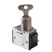
... Hp, 120V ac OFF-ON (Clockwise) 2 Hp, 240V ac 20A, 120V ac 20A, 240V S.T. OFF-ON-OFF-ON 1 1/2 Hp, 120V ac 2 Hp, 240V ac Q Key Style: A — 13-5496, E — 13-8173. W Not CSA Certified. 4.14 Circuits: General Purpose 1PST, 1PDT, 2PST, 2PDT. Maintained action. Heavy Duty 2PST, 2 Circuit. ...
Page 15
... Dia. 1.42 (.056) 12.01 (.473) 1.73 (.068) Mtg. Hole Key Removable In Both 13.84 15/32-32 Positions (.545) Thds. 34.92 0.25 20.90 (1.375) 17.45 (.010) (.823) (.687) 4.44 27.43 5.59 (1 ...
Page 16
... Nylon No 140L2 Nylon Yes 140CP2 Nylon No 140CPL2 INDUSTRIAL Nylon No PT2A21B Nylon Yes PT2A1A11B 60.33 0.38 (2.375) R 28.60 (R 1.125) Ø 4.35 (Ø .171) 14.90 0.38 (.587) 3.40 0.25 (.134) 12.70 10.40 (.500) 47.00 (.409) (1.850) 48.60 (1.913) 21.74 0.51 (.856) 42.29 (1.665 ...
Page 17
... JEPAC SERIES 8.00 .10 (.312) 15.40 10 (.601) 5.05 (.197) 49.10 .10 (1.915) 33.00 (1.287) 27.94 .25 33.00 24.00 (1.090) (1.287) (.936) 16.00 29.00 13.50 (.624) (1.131) 29.00 (.527) (1.131) 140PHX02 Utility ON/OFF PT2M21H Q Industrial ON/OFF 8600 Series AC Variable 64.00 (2.496) J1/J2 Series AC Variable 4 4.17 ...
Page 18
SPECIAL DEVICES AND ACCESSORIES Industrial Rocker Switch and Locking Rocker DESCRIPTION Locking Rocker This unique switch features a patented internal locking mechanism, which allows the switch to be locked in the off-position to prevent unauthorized or accidental operation. The ...
Page 19
... DIMENSIONS APPROXIMATE IN MM (INCHES) INDUSTRIAL ROCKER SWITCH 33.53 (1.320) Max. 7.11 (.280) 14.22 (.560) 23.11 8.89 (.910) (.350) #5 – 1/4 Lg. Head Screw 47.50 (1.870) LOCKING ROCKER SWITCH WITHOUT PALM GUARD 16.51 (.650) 43.18 27.43 (1.700) (1.080) 6.35 18.92 11.18 ( ...
Page 20
... SPECIAL DEVICES AND ACCESSORIES Sump Pump Switches — AC Rated These completely molded, ruggedly constructed switch assemblies are designed specifically for sump pump and liquid level applications. All series feature Quick-make/Quick-break mechanisms with snap acting butt contacts. They provide high reliability and long life at an economical cost ...
Page 21
DIMENSIONS APPROXIMATE IN MM (INCHES) PEDESTAL TYPE WEIGHT/FLOAT SWITCH 7.92 (.312) Dia. 20.57 43˚ (.810) 5.16 Ref. 4.78 (.188) Dia. (.203) 2 Holes 33.02 (1.300) 33.02 (1.300) 11.10 (.437) 69.85 (2.750) 4.75 (.187) 91.44 (3.060) 31.75 (1.250) 20.57 (.810) WEIGHT/FLOAT ...
Page 22
... 15-2525-6 — 12.01 (.473) 13.49 (.531) 15-2525-2 — 15.88 (.625) — 15-192 — 13.87 (.546) 15.88 (.625) 15-2525-58 — 13.87 (.546) 15.88 (.625) 15-2525-59 19.89 (.783) 25.80 (1.125) — 15-2528-2 — 14.27 (.562) 16.66 (.656) 15-966-2 — 14.27 (.562) 16.66 (.656) 15-966-6 — ...
Page 23
... 8280, 90, 95 15-192 — 11-1766 8282, 83, 92, 97 15-192 — 811-2 8307 — — 811-2 8337 — — 811-2 8370-75 15-192 — 11-1369 8381-82,86,91,96 15-192 — 811-2 8406 — — 811-2 8410 — — 811-2 8411, 18 15-192 29-761 11-1893 8432-35 15-192 — ...
Page 24
... No. 15-2528-2). Furnished unassembled. Plus 2 keys (Cat. No. 13-8171). Finish: Lock Bushing — Diecast zinc. Lock Barrel and Dress Nut — Chrome plated brass. Keys — Brass. 13-5496 Catalog No. 13-5496 13-8171 13-8173 DIMENSIONS APPROXIMATE IN MM (INCHES) Catalog Number CAT. NO. 15-1048 15-1048-3 15-1048-7 15-1049-3 15-1049-7 11 ...
Page 25
... A Washer A VIEW 11-26 811-14 811-2 Material Finish Catalog Number .320 Steel Burnished Nickel 30-5632-4 .032 Steel Burnished Nickel 30-5632-13 32-341 1 / 16" Lettering (located on angular surface). .105 .120 .467 Dia. Cupwasher .472 Stainless Steel Thickness of .427 .670 Silicone Dia. brusning seal is .432 ...
Page 26
... NGR Connector Catalog Number 28-5637-2 accepts NGR Connector Packard 12015870 Metri-Pack Terminals Catalog Number 28-5637-2 accepts or AMP compatible connector 28-5940 Packard 12015870 Metri-Pack Terminals accepts AMP terminals 42100-2. or AMP compatible connector 28-5940 accepts AMP terminals 42100-2 ...
Page 27
... Panel Opening Reference Only Thickness: 1.0 to 2.0 to 3.0 ( .039 to .078 to .118 ) Dimensions: 51.46 (2.026 +.254 –.000) plus number of center bezels times 1.030 Tolerence: +.254 –.000 for each center bezel maximum of +.050 EURO-LOOK, ESPORT & NGR PANEL PLUGS 35.05 (1 ...
Page 28
... SPECIAL DEVICES AND ACCESSORIES Rocker, Toggle and Pushbutton Switch Circuit Diagrams TERMINAL IDENTIFICATION TERMINAL MARKINGS When specified on order, switches will have the terminals identifi shown in the illustration at right. Single Pole 2 Terminal markings will be 3 ink-stamped on the side of the switch case and unused terminal ...
Page 29
... D.T Momentary contact. Q Terminal numbers 1, 2 and 3 denotes single pole base. Terminal numbers 11, 12, 13, 24, 25 and 26 denotes double pole base. W Single pole in double pole base with lamp independently wired. E Double Pole — Independently wired lamp. Q Circuit Number Schematic CENTER DOWN (Circuit ...