01-040.005 EAO, 01-040.005 Datasheet - Page 13
01-040.005
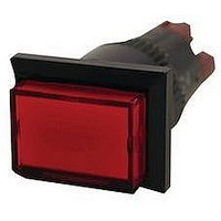
Manufacturer Part Number
01-040.005
Description
Pushbutton Switch
Manufacturer
EAO
Series
01r
Datasheet
1.01-040.005.pdf
(21 pages)
Specifications of 01-040.005
Contact Current Max
5A
Mounting Type
Panel
Switch Terminals
Solder Lug
Illumination
Illuminated
Switch Features
Lighted Indicator
Leaded Process Compatible
Yes
Size
HxWxD 0.708 X0.944 X1.65 In
Rohs Compliant
Yes
For Use With
01 Series Illuminated Pushbutton Switches
Lead Free Status / RoHS Status
Lead free / RoHS Compliant


Technical Data
switching system
material
mechanical characteristics
actuator with snap-action switching element
Self-cleaning, double-break, snap action switching system. (with
contact gap 2 x 0.5 mm).
1 normally closed or 1 normally open contact per element.
snap-action switching elements with soldering terminals at the
sides: up to 4 switching element can be on a pushbutton (max. 4
normally closed and 4 normally open contacts).
snap-action switching element with axial plug-in terminals 2,8 mm
not stachable, only 1 switching element can be on a pushbutton.
actuator case
polyphenylene PPO, self-extinguishing
material of contacts
gold-plated silver
switching element
axial plug-in-/soldering terminal 2.8 mm:
diallyl phthalate DAP, polyamide 66, polysulfone, heat-resistant
and self-extinguishing
soldering terminal: PA 6.6 Ultramid
actuating force
2-5.5 N, depending on the number of switching elements
actuating travel
3 mm
ambient air temperature
-25°C to +55°C
for indicators and illuminated pushbuttons mounted as a block ,
make sure the heat can escape freely
(as per DIN IEC 68-)
connection method
snap-action switching element with tinned soldering terminals at
the sides:
max. wire diameter: 2 wires of 1.2 mm
max. wire cross-section of stranded cable: 1x 1 mm
snap-action switching element with axial plug-in terminals, which
can also be used as soldering terminals:
plug-in terminal: 2.8 x 0.5 mm
soldering terminal:
max. wire diameter: 2 wires of 1 mm
max. wire cross-section of stranded cable: 2 x 0.75 mm
mm
degree of protection
front as per IEC 529:
IP 40
IP 67 with spray cover
mechanical life
momentary action 2 million cycles of operation
maintained action 1 million cycles of operation
rebound time
<= 5ms
resistance to climate
standard condition as per IEC 68-2-3 and 2-30
changing condition as per IEC 68-2-14 and 2-33
resistance to shock
(single impacts, semi-sinusoidal)
15 g for 11 ms as per IEC 512-4-3, IEC 68-2-27
2
2
2
.
2
or 1 x 1.0
electrical characteristics
rules
approvals
switching system
material
actuator with Low Level switching element
resistance to vibration
(sinusoidal)
10 g at 0-2000 Hz, amplitude 1.5 mm as per IEC 512-4-4, IEC 68-
2-6
storage temperature
-40°C to + 85°C
(as per DIN IEC 68-)
continuous thermal current lth
5 A
The maximum current in continuous operation and at ambient tem-
perature not exceeding the quoted maximum values.
electric strength
2500 VAC, 50 Hz, 1 min. between all terminals and earth, as per IC
512-2-11.
protection class
II
rated current
5 A
rated voltage
250 VAC/VDC
switch rating
250 VAC/5 A (cos
250 VAC/3 A (cos
switch rating AC, cos
voltage
current
switch rating DC (inductive), L:R = 30 ms:
voltage
current
volume resistance
starting value (initial) <= 50 m
IEC 1058 EN 61 058
- SEV 250 VAC/5A
- CSA 300 VAC
- UL
This low level switching element was designed for switching low
powers in electronic circuits. The mechanism assures reliable
switching of loads ranging from a few A/ V up to 100 mA/42 VAC/
VDC.
Single-break momentary contact, as normally open or normally
closed with 4 independent points of contact. 2 momentary contacts
per switching element; combination of normally open and normally
closed is possible.
Special features are the long life, extremely short rebound time and
stable contact resistance.
actuator case
polyphenylene PPO, self-extinguishing
material of contacts
gold-plated
125 V 250 V
3 A
24 V
2 A
2 A
60 V
0,7 A
1)
0.3)
0,7:
110 V 220 V
0,2 A
2
0,1 A
01.2000
25
01
0
Related parts for 01-040.005
Image
Part Number
Description
Manufacturer
Datasheet
Request
R

Part Number:
Description:
01 LOCKING CLIP HSG SR .156CL
Manufacturer:
TE Connectivity
Datasheet:

Part Number:
Description:
01 MODII HDR SRST B/A .100CL
Manufacturer:
TE Connectivity
Datasheet:
Part Number:
Description:
01 MODII HDR SRST B/A .100CL
Manufacturer:
TE Connectivity
Datasheet:
Part Number:
Description:
01 MODII HDR SRST B/A .100CL
Manufacturer:
TE Connectivity
Datasheet:
Part Number:
Description:
01 MODII HDR SRST B/A .100CL
Manufacturer:
TE Connectivity
Datasheet:

Part Number:
Description:
01 MODII HDR SRST UNSHRD A/PIN
Manufacturer:
TE Connectivity
Datasheet:


Part Number:
Description:
01 MODII HDR SRST B/A .100CL
Manufacturer:
TE Connectivity
Datasheet:

Part Number:
Description:
01 MODII HDR SRST B/A .100CL
Manufacturer:
TE Connectivity
Datasheet:

Part Number:
Description:
SINGLE CHIP LED/ T1 BI-PIN/ 2.1VDC/20MA - RED
Manufacturer:
EAO
Datasheet:

Part Number:
Description:
INDICATOR, INCAND LAMP, BI PIN
Manufacturer:
EAO
Datasheet:

Part Number:
Description:
INDICATOR, BI-PIN
Manufacturer:
EAO
Datasheet:

Part Number:
Description:
INDICATOR, INCAND LAMP, MIDGET GROOVED
Manufacturer:
EAO
Datasheet: