84-997 EAO, 84-997 Datasheet - Page 8
84-997
Manufacturer Part Number
84-997
Description
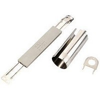
Mounting Tool
Manufacturer
EAO
Datasheet
1.84-0100.0.pdf
(50 pages)
Specifications of 84-997
Leaded Process Compatible
Yes
For Use With
84 Series Switches
Lead Free Status / RoHS Status
Lead free / RoHS Compliant


Mounting instruction
0
The arrangement of the mounting flanges and their number is determined by the size of
the front panel or PCB. To ensure uniform, tactile switching, we recommend a layout of
the flanges as per adjacent sketch.
For large PCBs with several switching elements we recommend the following procedure :
1. Fit the actuator to the front panel.
2. Clip the mounting flange to the rear of the intended actuator.
3. Screw the PCB with the components soldered to it to the assembled mounting flange.
This arrangement applies to PCBs 1.6 mm thick.
>
The tool 84-998 must be used for removing the mounting flange from the actuator. Before
removing the flange, the PCB fixing srews must be loosened.
Arrangement mounting flange for switching- and illumination element, PCB mounting
Dismantling mounting flange
6
05.2009
84
Related parts for 84-997
Image
Part Number
Description
Manufacturer
Datasheet
Request
R

Part Number:
Description:
Indicator
Manufacturer:
EAO
Datasheet:


Part Number:
Description:
Switch Actuator
Manufacturer:
EAO
Datasheet:

Part Number:
Description:
Switch Actuator
Manufacturer:
EAO
Datasheet:
Part Number:
Description:
Switch Actuator
Manufacturer:
EAO
Datasheet:
Part Number:
Description:
Switch Actuator
Manufacturer:
EAO
Datasheet:

Part Number:
Description:
INDICATOR, ALUMINUM
Manufacturer:
EAO
Datasheet:

Part Number:
Description:
SINGLE CHIP LED/ T1 BI-PIN/ 2.1VDC/20MA - RED
Manufacturer:
EAO
Datasheet:

Part Number:
Description:
INDICATOR, INCAND LAMP, BI PIN
Manufacturer:
EAO
Datasheet:

Part Number:
Description:
INDICATOR, BI-PIN
Manufacturer:
EAO
Datasheet:

Part Number:
Description:
INDICATOR, INCAND LAMP, MIDGET GROOVED
Manufacturer:
EAO
Datasheet: