HEDS-9730-350 Avago Technologies US Inc., HEDS-9730-350 Datasheet - Page 2
HEDS-9730-350
Manufacturer Part Number
HEDS-9730-350
Description
ENCODER SMALL 2CH 480LPI STR
Manufacturer
Avago Technologies US Inc.
Series
HEDSr
Specifications of HEDS-9730-350
Encoder Type
Optical
Output Type
Quadrature (Incremental)
Pulses Per Revolution
480 LPI
Voltage - Supply
3.3VDC
Actuator Type
Codestrip Not Included
Detent
No
Built In Switch
No
Mounting Type
Chassis Mount
Orientation
Vertical
Termination Style
Terminal Pins
Number Of Channels
2
Mounting Style
Bracket
Supply Voltage
3.3 V
Product
Optical
Technology
Rotary
Lead Free Status / RoHS Status
Contains lead / RoHS non-compliant
Rotational Life (cycles Min)
-
Lead Free Status / Rohs Status
Lead free / RoHS Compliant


The two channel digital outputs and 5 V supply input are
accessed through four solder-plated leads located on .54
mm (0.1 inch) centers.
The standard HEDS-973x is designed for use with an 11
mm optical radius codewheel, or linear codestrip. Other
options are available. Please contact factory for more in-
formation.
Applications
The HEDS-973x provides sophisticated motion detection
at a low cost, making closed-loop control very cost-com-
petitive! Typical applications include printers, plotters,
copiers, and office automation equipment.
Note: Avago Technologies encoders are not recommended for use in
safety critical applications. Eg. ABS braking systems, power steering, life
support systems and critical care medical equipment. Please contact
sales representative if more clarification is needed.
Theory of Operation
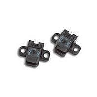
The HEDS-973X is a C-shaped emitter/detector module.
Coupled with a codewheel, it translates rotary motion into
a two-channel digital output. Coupled with a codestrip, it
translates linear motion into a digital output.
As seen in the block diagram, the module contains a single
Light Emitting Diode (LED) as its light source. The light is
collimated into a parallel beam by means of a single lens
located directly over the LED. Opposite the emitter is the
integrated detector circuit. This IC consists of multiple
sets of photodetectors and the signal processing circuitry
necessary to produce the digital waveforms.
The codewheel/codestrip moves between the emitter and
detector, causing the light beam to be interrupted by the
pattern of spaces and bars on the codewheel/codestrip.
The photodiodes which detect these interruptions are
arranged in a pattern that corresponds to the radius and
count density of the codewheel/codestrip. These detectors
are also spaced such that a light period on one pair of
detectors corresponds to a dark period on the adjacent
pair of detectors. The photodiode outputs are fed through
the signal processing circuitry. Two comparators receive
these signals and produce the final outputs for channels
A and B. Due to this integrated phasing technique, the
digital output of channel A is in quadrature with channel
B (90 degrees out of phase).
Block Diagram
Related parts for HEDS-9730-350
Image
Part Number
Description
Manufacturer
Datasheet
Request
R

Part Number:
Description:
ENCODER OPTICAL GAP 3CH 500CPR
Manufacturer:
Avago Technologies US Inc.
Datasheet:

Part Number:
Description:
Encoders 2 Channel 256CPR
Manufacturer:
Avago Technologies US Inc.
Datasheet:
Part Number:
Description:
Encoders 2 Channel 150CPR
Manufacturer:
Avago Technologies US Inc.
Datasheet:
Part Number:
Description:
Encoders 2 Channel 120CPR
Manufacturer:
Avago Technologies US Inc.
Datasheet:
Part Number:
Description:
SML ENC MOD 2CH BENT LDS 100 CPR
Manufacturer:
Avago Technologies US Inc.
Datasheet:
Part Number:
Description:
Encoders 2 Channel 400CPR
Manufacturer:
Avago Technologies US Inc.
Datasheet:

Part Number:
Description:
Encoders 2 Channel 180CPR
Manufacturer:
Avago Technologies US Inc.
Datasheet:
Part Number:
Description:
Encoders 2 Channel 400CPR
Manufacturer:
Avago Technologies US Inc.
Datasheet:
Part Number:
Description:
Encoders 2 Channel 150CPR
Manufacturer:
Avago Technologies US Inc.
Datasheet:
Part Number:
Description:
Encoders 2 Channel 150CPR
Manufacturer:
Avago Technologies US Inc.
Datasheet:
Part Number:
Description:
Encoders 2 Channel 150CPR
Manufacturer:
Avago Technologies US Inc.
Datasheet:
Part Number:
Description:
Encoders 2 Channel 150CPR
Manufacturer:
Avago Technologies US Inc.
Datasheet:
Part Number:
Description:
Encoders 2 Channel 360CPR
Manufacturer:
Avago Technologies US Inc.
Datasheet:
Part Number:
Description:
Encoders 2 Channel 150CPR
Manufacturer:
Avago Technologies US Inc.
Datasheet:
Part Number:
Description:
Encoders 2 Channel 400CPR
Manufacturer:
Avago Technologies US Inc.
Datasheet: