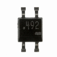
DN6849S Panasonic - SSG, DN6849S Datasheet - Page 4

DN6849S
Manufacturer Part Number
DN6849S
Description
IC HALL EFF SENSOR BI-DIR SOH-4D
Manufacturer
Panasonic - SSG
Type
Bipolar Latchr
Datasheets
1.DN6849S.pdf
(7 pages)
2.DN6849S.pdf
(3 pages)
3.DN6849S.pdf
(3 pages)
4.DN6849S.pdf
(7 pages)
Specifications of DN6849S
Sensing Range
-17.5mT Trip, 17.5mT Release
Voltage - Supply
4.5 V ~ 16 V
Current - Supply
6mA
Current - Output (max)
10µA
Output Type
Digital, Open Collector
Features
High Sensitivity
Operating Temperature
-40°C ~ 100°C
Package / Case
SOH-4D
Lead Free Status / RoHS Status
Contains lead / RoHS non-compliant
DN6849/SE/S
■ Caution on Use of Hall ICs
exposition to shock or vibration over a long period of time, and it causes the detection level change. To prevent this, fix
the package with adhesives or fix it on a dedicated case.
4
1. A case using an adhesive
2. A case bending lead wire
3. Power supply line/Power transmission line
4. On mounting of the surface mount type package (ESOP004-P-0200)
5. V
6. Cautions on power-on of Hall IC
the aluminum on the surface of the Hall IC, and may cause a functional defect of disconnection.
and substrate cleaner, as well as to the adhesive used for Hall IC installation. Please confirm the above matter to those
manufacturers before using.
line. In this case, set the capacitor of 0.1 µF to 10 µF near the Hall IC to prevent it.
ignition pulse, etc.), avoid it with external components (capacitor, resistor, Zener diode, diode, surge absorbing ele-
ments, etc.).
to V
the soldering. This may also cause a change in the operating magnetic flux density and a deterioration of its resistance
to moisture.
IC GND-pin voltage is set higher than other pin voltage, the IC configuration will become the same as a forward
biased diode. Therefore, it will turn on at the diode forward voltage (approximately 0.7 V), and a large current will
flow through the IC, ending up in its destruction. (This is common to monolithic IC.)
may be generated. Therefore, care should be given whenever the output state of a Hall IC is critical when the supply
power is on.
The Hall ICs are often used to detect movement. In such cases, the position of the Hall IC may be changed by
CC
If Hall IC is to be sealed after installation, attention should be given to the adhesive or resin used for peripherals
We could not select the specified adhesive, for we find it difficult to guarantee the ingredient of each adhesive.
Bend the lead wire without stressing the package.
If a voltage of 18 V or more is thought to be applied to the power supply line (flyback voltage from coil or the
Set pin 2 of the ESOP004-P-0200 package open, or connect it to GND. The IC will be damaged if it is connected
When mounted on the printed circuit board, the Hall IC may be highly stressed by the warp that may occur from
Do not reverse V
When a Hall IC is turned on, the position of the magnet or looseness may change the output of a Hall IC, and a pulse
CC
Some kinds of adhesive generate corrosive gas (such as chloric gas) during curing. This corrosive gas corrodes
If a power supply line/power transmission line becomes longer, noise and/or oscillation may be found on the
Fixed
and GND
.
Wrong
W
Bending method of lead wire
CC
and GND. If the V
W
Wrong
Fixed
Wrong
W
CC
Fixed
Correct
and GND pins are reversely connected, this IC will be destroyed. If the
SPC00004CEB
(a)
(b)
* : The distance can be within 3 mm, if no stress is applied
to the resin mold by tightly fixing the lead wires with a
metallic mold or the like.
Correct
Bending position of lead wire
Wrong
Wrong
Correct
Correct
3 mm *
3 mm *


