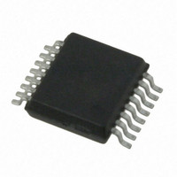
AS5130-ASST austriamicrosystems, AS5130-ASST Datasheet - Page 24

AS5130-ASST
Manufacturer Part Number
AS5130-ASST
Description
IC ENCODER ROTORY 8-BIT 16-SSOP
Manufacturer
austriamicrosystems
Type
Linear, Rotary Encoder - Programmabler
Datasheet
1.AS5130-ASST.pdf
(41 pages)
Specifications of AS5130-ASST
Sensing Range
32mT ~ 75mT
Voltage - Supply
4.5 V ~ 5.5 V
Current - Supply
24mA
Output Type
Analog, Ratiometric
Features
Programmable
Operating Temperature
-40°C ~ 125°C
Package / Case
16-SSOP
Lead Free Status / RoHS Status
Lead free / RoHS Compliant
Current - Output (max)
-
Other names
AS5130-ASSTTR
AS5130
Data Sheet - D e t a i l e d D e s c r i p t i o n
7.8.3 Polling Mode
Target of this mode is a reduction of the average power consumption. In this mode, the IC supply is pulsed, thereby reducing the average power
consumption to a fraction. The actual angle information and multi turn count value is not lost; polling mode is especially suited for battery
powered applications. The IC is furthermore capable of generating a WAKE signal as soon as the magnet’s position has changed, but only if the
supply of the IC is powered-on again. By means of the WAKE signal, the system’s power consumption can be further decreased, if certain
modules are activated on demand.
Figure 18. External Circuitry for Polling Mode
The voltage at pin 16 (DV
This voltage must always be present at DV
The procedure is as follows:
www.austriamicrosystems.com/AS5130
1. Initial startup: The circuit starts up with invalid trim values, which are read back from the storage registers; the command rst_otp (com-
2. These values are copied to the storage registers if OTP<8> (Wake enable) is set (must be set for polling mode).
3. The values of AGC counter, actual angle, multi turn counter, hysteresis setting, wake threshold and gain setting are continuously
4. The actual angle is stored as a reference by sending command STORE REF (command 3 – 00011). without this reference angle, a
5. The update of the storage registers is stopped if V
mand 19 – 10011) must be sent to read out valid trim values from the OTP.
updated in the storage registers.
WAKE is generated at every startup.
(V
the difference between both exceeds the threshold, a WAKE pulse is generated.
DD
on), the values are read back from the storage registers and the measured angle is compared with the stored reference angle; if
DD
) determines whether polling mode is activated or not. Any voltage above 3.6V activates the polling functionality.
V
DD
SS
in order to hold the information in the registers.
WAKE
DV
V
DD
DD
DD
drops below 4.45V and then the information is stored (DV
Revision 1.11
100n
t_on
t_off
>1.5K
+5V
t_wakeup
DD
) at the next startup
24 - 41


