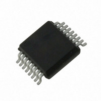
AS5043-ASST austriamicrosystems, AS5043-ASST Datasheet - Page 3

AS5043-ASST
Manufacturer Part Number
AS5043-ASST
Description
IC ENCODER PROG 10-BIT 16-SSOP
Manufacturer
austriamicrosystems
Type
Linear, Rotary Encoder - Programmabler
Datasheet
1.AS5043_PB.pdf
(36 pages)
Specifications of AS5043-ASST
Sensing Range
45mT ~ 75mT
Voltage - Supply
3 V ~ 3.6 V, 4.5 V ~ 5.5 V
Current - Supply
21mA
Current - Output (max)
4mA
Output Type
Analog, Digital
Features
Programmable
Operating Temperature
-40°C ~ 125°C
Package / Case
16-SSOP
Lead Free Status / RoHS Status
Lead free / RoHS Compliant
Other names
AS5043-ASSTTR
AS5043
Data Sheet - Pin Configuration
5.1 Pin Description
Pins 7, 15 and 16 are supply pins, pins 5, 13 and 14 are for internal use and must be left open.
Pin 1 is the magnetic field strength indicator, MagRNGn. It is an open-drain output that is pulled to VSS when the
magnetic field is out of the recommended range (45mT to 75mT). The chip will still continue to operate, but with reduced
performance, when the magnetic field is out of range. When this pin is low, the analog output at pins #10 and #12 will be
0V to indicate the out-of-range condition.
Pin 2 MODE allows switching between filtered (slow) and unfiltered (fast mode). This pin must be tied to VSS or VDD5V,
and must not be switched after power up. See section 0.
Pin 3 Chip Select (CSn; active low) selects a device for serial data transmission over the SSI interface. A “logic high” at
CSn forces output DO to digital tri-state.
Pin 4 CLK is the clock input for serial data transmission over the SSI interface (see section 1)
Pin 6 DO (Data Out) is the serial data output during data transmission over the SSI interface (see section 1)
Pin 8 PROG_DI is used to program the different operation modes, as well as the zero-position in the OTP register.
This pin is also used as a digital input to shift serial data through the device in Daisy Chain Configuration, (see page 9).
Pin 9 DACref is the external voltage reference input for the Digital-to-Analog Converter (DAC). If selected, the analog
output voltage on pin 12 (V
) will be ratiometric to the voltage on this pin.
out
Pin10 DACout is the unbuffered output of the DAC. This pin may be used to connect an external OPAMP, etc. to the
DAC.
Pin 11 FB (Feedback) is the inverting input of the OPAMP buffer stage.
Access to this pin allows various OPAMP configurations.
Pin 12 Vout is the analog output pin. The analog output is a DC voltage, ratiometric to VDD5V (3.0 – 5.5V) or an external
voltage source and proportional to the angle.
www.austriamicrosystems.com
Revision 1.80
3 – 36


