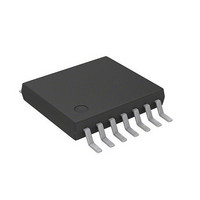
AS5163-HTSU austriamicrosystems, AS5163-HTSU Datasheet - Page 9

AS5163-HTSU
Manufacturer Part Number
AS5163-HTSU
Description
IC ENCODER PROG 12-BIT 14TSSOP
Manufacturer
austriamicrosystems
Type
Linear, Rotary Encoder - Programmabler
Datasheet
1.AS5163_CB.pdf
(36 pages)
Specifications of AS5163-HTSU
Featured Product
AS5163 - Contactless Magnetic Angle Position Sensor
Sensing Range
30mT ~ 70mT
Voltage - Supply
4.5 V ~ 5.5 V
Current - Supply
20mA
Output Type
Analog, Ratiometric
Operating Temperature
-40°C ~ 150°C
Package / Case
14-TSSOP (0.173", 4.40mm Width)
Lead Free Status / RoHS Status
Lead free / RoHS Compliant
Current - Output (max)
-
Features
-
AS5163
Datasheet - D e t a i l e d D e s c r i p t i o n
7.2 Analog Output
The reference voltage for the Digital-to-Analog converter (DAC) is taken internally from VDD. In this mode, the output voltage is ratiometric to the
supply voltage.
7.2.1 Programming Parameters
The Analog output voltage modes are programmable by OTP. Depending on the application, the analog output can be adjusted. The user can
program the following application specific parameters:
The above listed parameters are input parameters. Over the provided programming software and programmer, these parameters are converted
and finally written into the AS5163 128-bit OTP memory.
7.2.2 Application Specific Angular Range Programming
The application range can be selected by programming T1 with a related T1Y and T2 with a related T2Y into the AS5163. The internal gain factor
is calculated automatically. The clamping levels CLL and CLH can be programmed independent from the T1 and T2 position and both levels can
be separately adjusted.
Figure 5. Programming of an Individual Application Range
Figure 5
mechanical range. A sub range of the internal Cordic output range is used and mapped to the needed output characteristic. The analog output
signal has 12 bit, hence the level T1Y and T2Y can be adjusted with this resolution. As a result of this level and the calculated slope the clamping
region low is defined. The break point BP defines the transition between CLL and CLH. In this example, the BP is set to 0 degree. The BP is also
the end point of the clamping level high CLH. This range is defined by the level CLH and the calculated slope. Both clamping levels can be set
independently form each other. The minimum application range is 10 degrees.
www.austriamicrosystems.com/AS5163
180 degree
shows a simple example of the selection of the range. The mechanical starting point T1 and the mechanical end point T2 define the
CLH
T1Y
T2Y
CLL
BP
T1
T2
Mechanical angle start point
Mechanical angle end point
Voltage level at the T1 position
Voltage level at the T2 position
Clamping Level Low
Clamping Level High
Break point (transition point 0 to 360 degree)
CLH
90 degree
270 degree
T2
Application range
CLL
T1
BP
0 degree
100%VDD
Revision 2.7
CLH
CLL
T2Y
T1Y
0
clamping range
low
mechanical range
electrical range
T1
T2
clamping range
high
9 - 36


