SR13D-A1 Honeywell Sensing and Control, SR13D-A1 Datasheet - Page 3
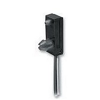
SR13D-A1
Manufacturer Part Number
SR13D-A1
Description
SENSOR UNIPOL HALL-EFFECT DGTL
Manufacturer
Honeywell Sensing and Control
Specifications of SR13D-A1
Sensor Terminals
Wire Lead
Supply Voltage Range Dc
3.8V To 30V
Output Configuration
Current Sink
Sensor Housing
Plastic
Switching Speed
1.5µs
Svhc
No SVHC (18-Jun-2010)
Lead Free Status / RoHS Status
Lead free / RoHS Compliant
Other names
480-3581
SR13D-A1
SR13D-A1


Solid State Hall Effect
Position Sensor
OPERATING CHARACTERISTICS –40 C TO 125 C, 3.8 TO 30 VDC
MAGNETIC CHARACTERISTICS
NOTICE
Bipolar Hall effect sensors may have an initial output in either the On or Off state if powered up with an applied
magnetic field in the differential zone (applied magnetic field > Brp and < Bop). Honeywell recommends allowing 10 µs
for output voltage to stabilize after supply voltage has reached 5 volts.
BLOCK CIRCUIT WIRING DIAGRAM
2 Honeywell Sensing and Control
Supply voltage
Current consumption
Output voltage (operated)
Sink current (operated)
Output leakage current
(released)
Output switching time
Operating Temperature
Magnetic Type
25 C
-20 C to 85 C
HALL
SENSOR
Max. Op.
Min. Rel.
Min. Dif.
Max. Op.
Min. Rel.
Min. Dif.
Rise, 10 to 90%
Fall, 90 to 10%
TRIGGER
CIRCUIT
AND
AMPLIFIER
SR13C-A1
Unipolar
180
75
25
215
60
10
Min.
3.8
-40 C to +150 C (-40 F to +302 F)
Typ.
1.5 s.
15 s
SR13D-A1
Unipolar
115
20
20
135
15
8
Max.
30
13
0.40
20
5 A
1.5 s
1.5 s
SR13F-A1
Unipolar
390
235
30
435
200
30
Remarks
VDC
mA
mA
V
V
Sinking 10 mA max.
OUT
CC
= 12 V, R
= 30 VDC, V
For application help: call 1-800-537-6945
L
= 1.6 K , C
OUTPUT
GROUND (-)
Vs (+)
(O) N. H.
Latching
85
-85
50
110
-110
50
CC
SR13R-A1
= 30 VDC
SR13/15 Series
L
= 20 pF
Unipolar
180
75
25
215
60
10
SR15C-A3
Related parts for SR13D-A1
Image
Part Number
Description
Manufacturer
Datasheet
Request
R

Part Number:
Description:
SERIES 942 SEPARATE COMPLETE SENSOR WITH HEAD AND CONTROL BOX, 3000 MM [118.0 IN] SCAN DISTANCE, TWO ANALOG OUTPUTS (0 VDC TO 10 VDC AND 4 MA TO 20 MA) , TWO SWITCHING OUTPUTS PNP AND DIGITAL LINK
Manufacturer:
Honeywell Sensing and Control
Part Number:
Description:
SERIES 942 SEPARATE COMPLETE SENSOR WITH HEAD AND CONTROL BOX, 900 MM [35.0 IN] SCAN DISTANCE, TWO ANALOG OUTPUTS (0 VDC TO 10 VDC AND 4 MA TO 20 MA) , TWO SWITCHING OUTPUTS PNP AND DIGITAL LINK
Manufacturer:
Honeywell Sensing and Control
Part Number:
Description:
SERIES 942 SEPARATE COMPLETE SENSOR WITH HEAD AND CONTROL BOX, 1500 MM [59.0 IN] SCAN DISTANCE, TWO ANALOG OUTPUTS (0 VDC TO 10 VDC AND 4 MA TO 20 MA) , TWO SWITCHING OUTPUTS PNP AND DIGITAL LINK
Manufacturer:
Honeywell Sensing and Control
Part Number:
Description:
SERIES 942 SEPARATE CONTROL BOX, 3000 MM [118.0 IN] SCAN DISTANCE, TWO ANALOG OUTPUTS (0 VDC TO 10 VDC AND 4 MA TO 20 MA) , TWO SWITCHING OUTPUTS PNP AND DIGITAL LINK, TO USE WITH 942 OR 947 SENSOR HE
Manufacturer:
Honeywell Sensing and Control
Part Number:
Description:
100FW SERIES, SHIELDED 3-WIRE DC SINKING (NPN), N.O. PROXIMITY SENSOR, 0.625 IN CYLINDRICAL HOUSING , 20 GA, MIL-W-16878/4 WIRE. NOMINAL SENSING DISTANCE OF 2,41 MM ±
Manufacturer:
Honeywell Sensing and Control
Part Number:
Description:
100FW SERIES, SHIELDED 3-WIRE DC SINKING (NPN), N.O. PROXIMITY SENSOR, 0.625 IN CYLINDRICAL HOUSING , CONNECTOR VERSION MATES WITH MS3116-10-6S. NOMINAL SENSING DISTANCE OF 2,41 MM ±
Manufacturer:
Honeywell Sensing and Control
Part Number:
Description:
HyCal Sensing Products
Manufacturer:
Honeywell Sensing and Control
Part Number:
Description:
200FW SERIES, SHIELDED 3-WIRE DC SINKING (NPN), N.O. PROXIMITY SENSOR, 0.625 IN CYLINDRICAL HOUSING , CONNECTOR VERSION MATES WITH MS3116-8-4S. NOMINAL SENSING DISTANCE OF 2,4 MM TO 11,4 MM [.09 IN
Manufacturer:
Honeywell Sensing and Control
Part Number:
Description:
FF-SRL SERIES, PRESENCE SENSING DEVICE INITIATION MODULE, 24 VDC
Manufacturer:
Honeywell Sensing and Control
Part Number:
Description:
HyCal Sensing Products
Manufacturer:
Honeywell Sensing and Control
Part Number:
Description:
HyCal Sensing Products
Manufacturer:
Honeywell Sensing and Control
Part Number:
Description:
HyCal Sensing Products
Manufacturer:
Honeywell Sensing and Control
Part Number:
Description:
SERIES 942 SEPARATE SENSOR HEAD, 1500 MM [59.0 IN] SCAN DISTANCE, STAINLESS STEEL M30, CONNECTOR, TO USE WITH 942-M0A CONTROL BOX
Manufacturer:
Honeywell Sensing and Control