AMN33111 Panasonic Electric Works, AMN33111 Datasheet - Page 6
AMN33111
Manufacturer Part Number
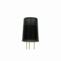
AMN33111
Description
SENSOR MOTION SPOT 5V BLK LENS
Manufacturer
Panasonic Electric Works
Series
NaPiOn™r
Specifications of AMN33111
Sensing Distance
16.40' (5m)
Sensor Type
Passive Motion
Sensing Object
*
Response Frequency
*
Material - Body
*
Shielding
*
Voltage - Supply
3 V ~ 6 V
Output Type
Digital
Terminal Type
PC Pin
Package / Case
Radial
Lead Free Status / RoHS Status
Lead free / RoHS Compliant
Other names
255-2647


HOW TO USE
1. Wiring diagram
1) Digital output
2. Timer circuit example
1) Digital output
Note: This is the reference circuit which drives the MP motion sensor. Install a noise
3. Installation
Install the sensor so that people will be entering from the X or Y
direction shown below. If persons approch the sensor from the Z
direction, detection distance will be shortened.
The transistor
turns on when
the sensor
detects
something
Vdd: Input power source (DC)
GND: GND
Out: Output (Comparator)
Input voltage
filter for applications requiring enhanced detection reliability and noise
withstanding capability.
Differences in the specifications of electronic components to which the units
are connected sometimes affect their correct operation; please check the
units’ performance and reliability for each application.
Sensor
GND
Relay
Select a transistor
to match the relay
10 µ
10 µ
47k
+
0.1 µ
+
13
74HC
123 etc.
Timer IC
3
5V
REG
10
11
2
9
8
0.1 µ
16
15
14
1
Iout: Max.100 µA
Vdd
GND
Out
47 µ
0.1 µ
R
C
All Rights Reserved © COPYRIGHT Matsushita Electric Works, Ltd.
+
Timer time = RXC
0.1 µ
10k
(5VDC)
+
0.1 µ
Load
Vdd
Out
GND
Connection
to motion
sensor
+
2) Analog output
Note: This circuit is a sample of a drive circuit for the MP Motion Sensor. Its noise
2) Analog output
The transistor
turns on when
the sensor
detects
something
Input voltage
resistance and long-term reliability are not considered or investigated.
To improve the detection reliability and noise resistance of the circuit, consider
adding a noise filter.
Matsushita Electric Works, Ltd. accepts no responsibility for damages
resulting from the use of this circuit.
Sensor
GND
MP Motion Sensor (AMN2, 3, 4)
Relay
X direction ❍
Y direction ❍
Select a
transistor
to match
the relay
10 µ
OP
AMP
10 µ
47k
+
0.1 µ
+
Timer IC
13
74HC
123 etc.
3
10
11
2
9
8
16
5V
REG
15
14
X direction ❍
1
0.1 µ
0.1 µ
R
C
Timer time = RXC
47 µ
0.1 µ
Vdd
GND
Out
10k
Z direction ∆
+
Z
Window
comparator
(5VDC)
0.1 µ
Vdd
Out
GND
Microcomputer,
A/D converter
etc.
Connection
to motion
sensor
Related parts for AMN33111
Image
Part Number
Description
Manufacturer
Datasheet
Request
R

Part Number:
Description:
Manufacturer:
Panasonic Electric Works
Datasheet:
Part Number:
Description:
Manufacturer:
Panasonic Electric Works
Datasheet:

Part Number:
Description:
CONN SOCKET P4 .4MM 50POS SMD
Manufacturer:
Panasonic Electric Works
Datasheet:
Part Number:
Description:
CONN SOCKET .8MM 16POS SMD
Manufacturer:
Panasonic Electric Works
Datasheet:
Part Number:
Description:
CONN HEADER .8MM 16POS SMD
Manufacturer:
Panasonic Electric Works
Datasheet:
Part Number:
Description:
CONN SOCKET .8MM 20POS SMD
Manufacturer:
Panasonic Electric Works
Datasheet:
Part Number:
Description:
CONN SOCKET .8MM 20POS SMD
Manufacturer:
Panasonic Electric Works
Datasheet:
Part Number:
Description:
CONN HEADER .8MM 20POS SMD
Manufacturer:
Panasonic Electric Works
Datasheet:
Part Number:
Description:
CONN SOCKET .8MM 22POS SMD
Manufacturer:
Panasonic Electric Works
Datasheet:
Part Number:
Description:
CONN SOCKET .8MM 30POS SMD
Manufacturer:
Panasonic Electric Works
Datasheet:
Part Number:
Description:
CONN HEADER .8MM 30POS SMD
Manufacturer:
Panasonic Electric Works
Datasheet:
Part Number:
Description:
CONN SOCKET .8MM 30POS SMD
Manufacturer:
Panasonic Electric Works
Datasheet:
Part Number:
Description:
CONN SOCKET .8MM 30POS SMD
Manufacturer:
Panasonic Electric Works
Datasheet:
Part Number:
Description:
CONN HEADER .8MM 30POS SMD
Manufacturer:
Panasonic Electric Works
Datasheet:
Part Number:
Description:
CONN HEADER BRD/BRD .5MM 60POS
Manufacturer:
Panasonic Electric Works
Datasheet: