NTCSMELFE3103JT Vishay, NTCSMELFE3103JT Datasheet - Page 2
NTCSMELFE3103JT
Manufacturer Part Number
NTCSMELFE3103JT
Description
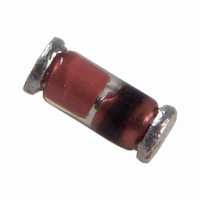
THERMISTOR NTC 10K 5% MELF
Manufacturer
Vishay
Series
2381r
Type
NTCr
Datasheet
1.NTCSMELFE3103JT.pdf
(5 pages)
Specifications of NTCSMELFE3103JT
Resistance In Ohms @ 25°c
10K
Resistance Tolerance
±5%
B Value Tolerance
±1.3%
B25/85
3997K
Operating Temperature
-40°C ~ 200°C
Power - Max
100mW
Mounting Type
Surface Mount
Package / Case
MELF
Resistance
10 KOhms
Tolerance
5 %
Termination Style
Axial
Description Of Terminals
Leadless
Mounting Style
Surface Mount
Pin Count
2
Screening Level
Automotive
Sensitivity Index
3977K
Resistance @ 25c
10kohm
Thermal Time Constant
6s
Percentage Of Resistance Tolerance @ 25c
±5
Accuracy
±1.3
Operating Temperature Min Deg. C
-40C
Operating Temperature Max Deg. C
150C
Product Length (mm)
3.5mm
Product Height (mm)
Not Requiredmm
Product Depth (mm)
Not Requiredmm
Lead Free Status / RoHS Status
Lead free / RoHS Compliant
B0/50
-
B25/50
-
B25/75
-
B25/100
-
Lead Length
-
Lead Free Status / Rohs Status
Compliant
Other names
2381 633 53103
2381 633 53103
238163353103
BC2544TR
2381 633 53103
238163353103
BC2544TR


www.vishay.com
60
2381 633 5..../NTCSMELFE3....T
Vishay BCcomponents
DIMENSIONS in millimeters
DERATING
STABILITY CHARACTERISTICS
Stability of glass encapsulated NTCs in thermal shock test (200 kcycles - 40 °C/+ 200 °C)
(%)
ΔR
R
0.8
0.6
0.4
0.2
0
10
3
Derating curve for 2381 633 5.... series
(%)
100
P
- 40
0
For technical questions, contact:
Component outline for 2381 633 5.... (SOD80)
SMD MELF SOD80, Glass Encapsulated
0.35 ± 0.1
10
4
0
3.5 ± 0.35
NTC Thermistor
55
85
nlr@vishay.com
Ø 1.55 ± 0.15
T
amb
0.35 ± 0.1
(°C)
10
5
150
ΔT (at 25 °C)
ΔT (at 85 °C)
ΔR
ΔR
85
25
/R
/R
Cycles
85
25
Document Number: 29119
10
6
0
Revision: 23-Nov-09
- 0.1
- 0.2
- 0.3
- 0.4
(K)
ΔT
Related parts for NTCSMELFE3103JT
Image
Part Number
Description
Manufacturer
Datasheet
Request
R

Part Number:
Description:
357-036-542-201 CARDEDGE 36POS DL .156 BLK LOPRO
Manufacturer:
Vishay
Datasheet:
Part Number:
Description:
357-036-542-201 CARDEDGE 36POS DL .156 BLK LOPRO
Manufacturer:
Vishay
Datasheet:
Part Number:
Description:
357-036-542-201 CARDEDGE 36POS DL .156 BLK LOPRO
Manufacturer:
Vishay
Datasheet:
Part Number:
Description:
357-036-542-201 CARDEDGE 36POS DL .156 BLK LOPRO
Manufacturer:
Vishay
Datasheet:
Part Number:
Description:
357-036-542-201 CARDEDGE 36POS DL .156 BLK LOPRO
Manufacturer:
Vishay
Datasheet:
Part Number:
Description:
357-036-542-201 CARDEDGE 36POS DL .156 BLK LOPRO
Manufacturer:
Vishay
Datasheet:
Part Number:
Description:
357-036-542-201 CARDEDGE 36POS DL .156 BLK LOPRO
Manufacturer:
Vishay
Datasheet:
Part Number:
Description:
357-036-542-201 CARDEDGE 36POS DL .156 BLK LOPRO
Manufacturer:
Vishay
Datasheet:
Part Number:
Description:
357-036-542-201 CARDEDGE 36POS DL .156 BLK LOPRO
Manufacturer:
Vishay
Datasheet:
Part Number:
Description:
357-036-542-201 CARDEDGE 36POS DL .156 BLK LOPRO
Manufacturer:
Vishay
Datasheet:
Part Number:
Description:
357-036-542-201 CARDEDGE 36POS DL .156 BLK LOPRO
Manufacturer:
Vishay
Datasheet:
Part Number:
Description:
357-036-542-201 CARDEDGE 36POS DL .156 BLK LOPRO
Manufacturer:
Vishay
Datasheet:
Part Number:
Description:
357-036-542-201 CARDEDGE 36POS DL .156 BLK LOPRO
Manufacturer:
Vishay
Datasheet:
Part Number:
Description:
357-036-542-201 CARDEDGE 36POS DL .156 BLK LOPRO
Manufacturer:
Vishay
Datasheet:
Part Number:
Description:
357-036-542-201 CARDEDGE 36POS DL .156 BLK LOPRO
Manufacturer:
Vishay
Datasheet: