NTCLE100E3153JB0 Vishay, NTCLE100E3153JB0 Datasheet - Page 16
NTCLE100E3153JB0
Manufacturer Part Number
NTCLE100E3153JB0
Description
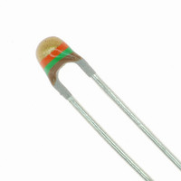
THERMISTOR NTC 15K OHM LEADED
Manufacturer
Vishay
Series
2381r
Type
NTCr
Specifications of NTCLE100E3153JB0
Resistance In Ohms @ 25°c
15K
Resistance Tolerance
±5%
B Value Tolerance
±2%
B25/85
3740K
Operating Temperature
-40°C ~ 125°C
Power - Max
500mW
Lead Length
0.59" (15.00mm)
Mounting Type
Through Hole
Package / Case
Bead, Glass
Mounting Style
Through Hole
Pin Count
2
Screening Level
Automotive
Sensitivity Index
3740K
Resistance @ 25c
15kohm
Thermal Time Constant
15s
Percentage Of Resistance Tolerance @ 25c
±5
Accuracy
±2
Operating Temperature Min Deg. C
-40C
Operating Temperature Max Deg. C
125C
Product Length (mm)
3.3mm
Product Height (mm)
9mm
Product Depth (mm)
3mm
Resistance
15000 Ohms
Tolerance
5 %
Operating Temperature Range
0 C to + 55 C
Dimensions
5 mm L
Lead Spacing
2.54 mm
Thermistor Type
NTC
Thermistor Tolerance
± 5%
Beta Value (k)
3740
Thermistor Case Style
Radial Leaded
No. Of Pins
2
Beta Lower Temperature
25°C
Rohs Compliant
Yes
Lead Free Status / RoHS Status
Lead free / RoHS Compliant
B0/50
-
B25/50
-
B25/75
-
B25/100
-
Lead Free Status / Rohs Status
Lead free / RoHS Compliant
Other names
2381 640 63153
238164063153
BC2303
238164063153
BC2303


NTCLE100E3...B0/T1/T2/2381 640 3/4/6....
Vishay BCcomponents
REEL SPECIFICATIONS
TESTS AND REQUIREMENTS
Essentially all tests are carried out in accordance with “IEC publication 60068-2; Environmental testing”, except where indicated.
Notes
(1)
(2)
www.vishay.com
90
STABILITY TESTS
CECC 32 100
CLAUSE
D3; 4.20.1
D1; 4.19
C2; 4.14
Other applicable tests
For R
For R
56 max.
42 ±1
25
25
from 2.2 kΩ to 10 kΩ, requirement is ± 2 % max.
≥ 100 kΩ the drift requirement is ΔR/R < 5 %
Dimensions of the reel
3
18
22.5
16
TEST METHOD
+1
- 0
60695-2-2
60068-2
77
IEC
539
14
21
58
27
29
45
1
2
3
6
85.6
92
max.
Resistance to solvent (isopropanol)
356
Rapid change of temperature
Robustness of leads:
Resistance to heat
NTC Thermistors, Radial Leaded,
Tensile strength
For technical questions, contact:
Inflammability
(steady state)
(steady state)
Note
(1)
CHARACTERISTICS OF TAPED PRODUCTS
Minimum pull-out force of the component: 5 N
Minimum peel-off force of adhesive tape: 6 N
Minimum tearing force tape: 15 N
Minimum pull-off force of tape-reel: 5 N
STORAGE CONDITIONS
Storage temperature range: - 25 °C to + 40 °C
Maximum relative humidity: 80 %, non-condensing
Solderability
Endurance
Endurance
Endurance
Damp heat
Soldering:
Dry heat,
Vibration
CODE NUMBERS AND RELEVANT PACKAGING QUANTITIES
PARAMETER
Quantity
Bending
Taped according IEC 60286-2
Impact
Shock
TEST
Standard Precision
each direction in three orthogonal directions
NTCLE100E3....B0
10 gp: 50 Hz to 500 Hz 1 octave/min. 2 h in
2381 640 6..../
1.5 mm peak to peak: 10 Hz to 58 Hz
nlr@vishay.com
56 days at 40 °C; 90 to 95 % RH
5 N with hydrophylic cotton wool
240 °C max.; duration 4 s max.
265 °C max.; duration 5 s max.
BULK
- 40 °C to + 125 °C; 50 cycles
Ambient temp for 5 minutes;
500
500 mW; 55 °C; 1000 h
1980, needle flame test
490 m/s; half sinewave
Loading force 10 N
Loading force 5 N
- 40 °C; 1000 h
125 °C; 1000 h
PROCEDURE
25 °C; 1000 h
Free fall; 1 m
1500 per reel, 2 reels
TAPE AND REEL
NTCLE100E3....T1
2381 640 4..../
1E PITCH
per box
(1)
Document Number: 29049
1500 per reel, 2 reels
TAPE AND REEL
No traces of lacquer
NTCLE100E3....T2
No visible damage
REQUIREMENTS
Revision: 17-Jun-10
Non-flammable
2381 640 3..../
on cotton wool
ΔR/R < 3 %
ΔR/R ≤ 1 %
ΔR/R < 1 %
ΔR/R < 1 %
ΔR/R < 3 %
ΔR/R < 3 %
ΔR/R < 2 %
ΔR/R ≤ 1 %
ΔR/R ≤ 1 %
ΔR/R ≤ 1 %
ΔR/R < 1 %
2E PITCH
per box
(1)
(2)
(1)
Related parts for NTCLE100E3153JB0
Image
Part Number
Description
Manufacturer
Datasheet
Request
R

Part Number:
Description:
Thermistors - NTC NTC CU 10K 5% 0.6 Lead
Manufacturer:
Vishay
Datasheet:
Part Number:
Description:
357-036-542-201 CARDEDGE 36POS DL .156 BLK LOPRO
Manufacturer:
Vishay
Datasheet:
Part Number:
Description:
357-036-542-201 CARDEDGE 36POS DL .156 BLK LOPRO
Manufacturer:
Vishay
Datasheet:
Part Number:
Description:
357-036-542-201 CARDEDGE 36POS DL .156 BLK LOPRO
Manufacturer:
Vishay
Datasheet:
Part Number:
Description:
357-036-542-201 CARDEDGE 36POS DL .156 BLK LOPRO
Manufacturer:
Vishay
Datasheet:
Part Number:
Description:
357-036-542-201 CARDEDGE 36POS DL .156 BLK LOPRO
Manufacturer:
Vishay
Datasheet:
Part Number:
Description:
357-036-542-201 CARDEDGE 36POS DL .156 BLK LOPRO
Manufacturer:
Vishay
Datasheet:
Part Number:
Description:
357-036-542-201 CARDEDGE 36POS DL .156 BLK LOPRO
Manufacturer:
Vishay
Datasheet:
Part Number:
Description:
357-036-542-201 CARDEDGE 36POS DL .156 BLK LOPRO
Manufacturer:
Vishay
Datasheet:
Part Number:
Description:
357-036-542-201 CARDEDGE 36POS DL .156 BLK LOPRO
Manufacturer:
Vishay
Datasheet:
Part Number:
Description:
357-036-542-201 CARDEDGE 36POS DL .156 BLK LOPRO
Manufacturer:
Vishay
Datasheet:
Part Number:
Description:
357-036-542-201 CARDEDGE 36POS DL .156 BLK LOPRO
Manufacturer:
Vishay
Datasheet:
Part Number:
Description:
357-036-542-201 CARDEDGE 36POS DL .156 BLK LOPRO
Manufacturer:
Vishay
Datasheet:
Part Number:
Description:
357-036-542-201 CARDEDGE 36POS DL .156 BLK LOPRO
Manufacturer:
Vishay
Datasheet:
Part Number:
Description:
357-036-542-201 CARDEDGE 36POS DL .156 BLK LOPRO
Manufacturer:
Vishay
Datasheet: