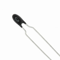
B57871S0212F000 EPCOS Inc, B57871S0212F000 Datasheet - Page 12

B57871S0212F000
Manufacturer Part Number
B57871S0212F000
Description
THERMISTOR NTC 2.1K OHM 1% RAD
Manufacturer
EPCOS Inc
Series
B57871r
Datasheet
1.B57891M103K.pdf
(19 pages)
Specifications of B57871S0212F000
Resistance In Ohms @ 25°c
2.1K
Resistance Tolerance
±1%
B Value Tolerance
±1%
B25/100
3560K
Operating Temperature
-55°C ~ 155°C
Power - Max
60mW
Lead Length
1.42" (36.00mm)
Mounting Type
Through Hole
Package / Case
Bead
Lead Free Status / RoHS Status
Lead free / RoHS Compliant
B0/50
-
B25/50
-
B25/75
-
B25/85
-
Other names
495-3035
B57871S 212F
B57871S212F
B57871S 212F
B57871S212F
Available stocks
Company
Part Number
Manufacturer
Quantity
Price
Company:
Part Number:
B57871S0212F000
Manufacturer:
ILLINOSI
Quantity:
37 000
Mounting instructions
1
1.1
Leaded thermistors comply with the solderability requirements specified by CECC.
When soldering, care must be taken that the NTC thermistors are not damaged by excessive
heat. The following maximum temperatures, maximum time spans and minimum distances have
to be observed:
Bath temperature
Soldering time
Distance from thermistor
Under more severe soldering conditions the resistance may change.
1.2
In case of NTC thermistors without leads, soldering is restricted to devices which are provided
with a solderable metallization. The temperature shock caused by the application of hot solder
may produce fine cracks in the ceramic, resulting in changes in resistance.
To prevent leaching of the metallization, solder with silver additives or with a low tin content
should be used. In addition, soldering methods should be employed which permit short soldering
times.
2
Pressure contacting by means of clamps is particularly suitable for applications involving frequent
switching and high turn-on powers.
3
The leads meet the requirements of IEC 60068-2-21. They may not be bent closer than 4 mm
from the solder joint on the thermistor body or from the point at which they leave the feed-
throughs. During bending, any mechanical stress at the outlet of the leads must be removed. The
bending radius should be at least 0.75 mm.
Tensile strength:
Please read Cautions and warnings and
Important notes at the end of this document.
Temperature measurement
Leaded NTC thermistors, lead spacing 2.5 mm
Soldering
Leaded NTC thermistors
Leadless NTC thermistors
Clamp contacting
Robustness of terminations (leaded types)
Test Ua1:
Leads
0.25 <
0.35 <
0.50 <
0.80 <
Dip soldering
max. 260 C
max. 4 s
min. 6 mm
0.25 mm =
0.35 mm =
0.50 mm =
0.80 mm = 10.0 N
1.25 mm = 20.0 N
Page 12 of 19
Iron soldering
max. 360 C
max. 2 s
min. 6 mm
1.0 N
2.5 N
5.0 N
B57871S
S871


