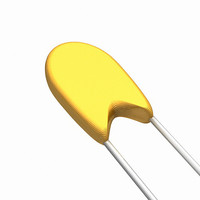
09M1002JF Vishay, 09M1002JF Datasheet - Page 4

09M1002JF
Manufacturer Part Number
09M1002JF
Description
THERM NTC 10K OHM 5% 30 AWG RAD
Manufacturer
Vishay
Series
Mr
Datasheet
1.01C1002JF.pdf
(5 pages)
Specifications of 09M1002JF
Resistance In Ohms @ 25°c
10K
Resistance Tolerance
±5%
Lead Length
1.42" (36.00mm)
Mounting Type
Free Hanging
Package / Case
Bead
Lead Free Status / RoHS Status
Lead free by exemption / RoHS Compliant
B Value Tolerance
-
B0/50
-
B25/50
-
B25/75
-
B25/85
-
B25/100
-
Operating Temperature
-
Power - Max
-
Other names
09M1002JF
541-1081
541-1081
POINT MATCH TOLERANCE
The standard leaded thermistors are calibrated and tested at 25 °C to a tolerance of ± 5 % or ± 10 %; however, tighter tolerance,
point matched thermistors are readily available as are special point match temperatures to fit your application.
Since these thermistors have only one controlled point of reference (the point match temperature), the resistance at other
temperatures is given by the “Resistance vs. Temperature Conversion Tables” for the appropriate material curve. The resistance
value at any temperature is the ratio factor times the resistance at 25 °C. The resistance vs. temperature conversion tables can
be found at:
Example: 09M1002JF, + 70 °C resistance = (Resistance factor for curve 9 at 70 °C is 0.1990) x (10 000 Ω resistance at 25 °C)
= 1990 Ω.
The tolerance of the resistance at any temperature is described by figure 2.
FIGURE 2
POINT MATCH TOLERANCES VS. TEMPERATURE
COMPUTER AIDS FOR THERMISTOR SELECTION
A spreadsheet is available for the Vishay thermistor materials that calculates beta, Steinhart-Hart equation constants A, B, and
C, the resistance at any temperature based upon the Steinhart constants or beta, the temperature equivalent of the resistance
reading, and resistance temperature coefficients.
This spread sheet will also calculate the total resistance tolerance of any point matched thermistor for temperatures in 10 ºC
increments, and the resistance tolerance at any temperature within the calibrated range of curve tracking thermistors. Please
contact factory if interested in this Excel™ spreadsheet at thermistor1@vishay.com.
Document Number: 33003
Revision: 12-Nov-09
www.vishay.com/doc?33004
MAX. R vs. T
MIN. R vs. T
NOMINAL R vs. T
25 °C
TEMPERATURE
(CALIBRATION TEMPERATURE)
NTC Thermistors, Radial Leaded and Coated
For technical questions, contact:
PIVOT POINT
and www.vishay.com/doc?33011.
Point match resistance tolerances at temperatures other
than 25 ºC are not the same as the calibration temperature.
This difference is presented in figure 2.
The tolerance at any given temperature is the point match
tolerance + the MT ± % (manufacturing tolerance).
The MT ± % may be obtained from the R vs. T conversion
tables (see www.vishay.com/doc?33004) and is added to the
point match temperature, i.e., ± 1 % Tol. at 25 ºC + ± 2.6 %
at - 30 ºC for Curve 1 equals a total tolerance of ± 3.6 % at
- 30 ºC.
thermistor1@vishay.com
Vishay Dale
www.vishay.com
M, C, T
107


