PTCSL20T091DBE Vishay, PTCSL20T091DBE Datasheet - Page 8
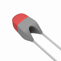
PTCSL20T091DBE
Manufacturer Part Number
PTCSL20T091DBE
Description
THERMISTR 90DEG C TRANS TEMP PTC
Manufacturer
Vishay
Series
2322r
Type
PTCr
Datasheets
1.PTCSL20T091DBE.pdf
(9 pages)
2.PTCSL20T091DBE.pdf
(5 pages)
3.PTCSL20T101DBX.pdf
(5 pages)
Specifications of PTCSL20T091DBE
Resistance In Ohms @ 25°c
120
Resistance Tolerance
±20%
Operating Temperature
70°C ~ 170°C
Mounting Type
PCB, Through Hole
Package / Case
Radial
Mounting Style
Through Hole
Pin Count
2
Resistance @ 25c
100Ohm
Product Length (mm)
3.5mm
Product Height (mm)
7mm
Product Depth (mm)
3mm
Resistance
100 Ohms
Termination Style
Radial
Lead Free Status / RoHS Status
Contains lead / RoHS non-compliant
Power - Max
-
Lead Free Status / Rohs Status
Lead free / RoHS Compliant
Other names
2322 671 91104
232267191104
BC1378
PTCSL20T091DBX
232267191104
BC1378
PTCSL20T091DBX
Available stocks
Company
Part Number
Manufacturer
Quantity
Price


BCcomponents
TEST AND REQUIREMENTS
Clause numbers of tests and performance requirements refer to the “IEC 60738-1-4”.
Tables with requirements for lot-by-lot and periodic tests.
In these tables:
D = Destructive
ND = Non-destructive.
Acceptable quality level
2001 May 02
Group A inspection (lot-by-lot)
S
4.5
S
4.4.1
S
4.4.3
Group B inspection (lot-by-lot)
S
4.16.1
Group C inspection (periodic)
S
4.15
4.16.2
UB
UB
UB
UB
UB
PTC thermistors for temperature
protection
CLAUSE
-
-
-
-
-
IEC
GROUP
GROUP
GROUP
GROUP
GROUP
A0
A1
A2
B2
C1A
zero power resistance
visual examination
dimensions (gauging)
soldering, solderability
robustness of terminations
resistance to soldering heat
TEST
ND
ND
ND
D
D
D or ND
temperature: 25 C
voltage: 1.5 V
(T
(T
(T
for 2322 671 91052 to 91067 and
91002 to 91017:
solder bath: 60/40; 260 5 C and
RMA flux; duration: 30 s
for 2322 671 91102 to 91114 and
91102 to 91114:
solder bath method: 235 5 C
for 2322 671 91102 to 91114:
test Ua (10 N) and test Ub (5 N) of
“IEC 60068-2-21”
visual examination
zero power resistance at 25 C
for 2322 671 91102 to 91114:
test Tb of “IEC 60068-2-20A”
visual examination
zero power resistance at 25 C
n
n
n
+ 5) C
+ 15) C
8
5) C
PROCEDURE
T
n
= 70 to 170 C
30 to 120
as specified
as specified
no defect likely to impair
function
as specified
75% of surface covered
with solder
the terminations shall be
evenly tinned
as in 4.12.4; see note 1
as in 4.13.2.3
4000
R/R
R/R
REQUIREMENTS
Product specification
10%
10%
Related parts for PTCSL20T091DBE
Image
Part Number
Description
Manufacturer
Datasheet
Request
R

Part Number:
Description:
357-036-542-201 CARDEDGE 36POS DL .156 BLK LOPRO
Manufacturer:
Vishay
Datasheet:
Part Number:
Description:
357-036-542-201 CARDEDGE 36POS DL .156 BLK LOPRO
Manufacturer:
Vishay
Datasheet:
Part Number:
Description:
357-036-542-201 CARDEDGE 36POS DL .156 BLK LOPRO
Manufacturer:
Vishay
Datasheet:
Part Number:
Description:
357-036-542-201 CARDEDGE 36POS DL .156 BLK LOPRO
Manufacturer:
Vishay
Datasheet:
Part Number:
Description:
357-036-542-201 CARDEDGE 36POS DL .156 BLK LOPRO
Manufacturer:
Vishay
Datasheet:
Part Number:
Description:
357-036-542-201 CARDEDGE 36POS DL .156 BLK LOPRO
Manufacturer:
Vishay
Datasheet:
Part Number:
Description:
357-036-542-201 CARDEDGE 36POS DL .156 BLK LOPRO
Manufacturer:
Vishay
Datasheet:
Part Number:
Description:
357-036-542-201 CARDEDGE 36POS DL .156 BLK LOPRO
Manufacturer:
Vishay
Datasheet:
Part Number:
Description:
357-036-542-201 CARDEDGE 36POS DL .156 BLK LOPRO
Manufacturer:
Vishay
Datasheet:
Part Number:
Description:
357-036-542-201 CARDEDGE 36POS DL .156 BLK LOPRO
Manufacturer:
Vishay
Datasheet:
Part Number:
Description:
357-036-542-201 CARDEDGE 36POS DL .156 BLK LOPRO
Manufacturer:
Vishay
Datasheet:
Part Number:
Description:
357-036-542-201 CARDEDGE 36POS DL .156 BLK LOPRO
Manufacturer:
Vishay
Datasheet:
Part Number:
Description:
357-036-542-201 CARDEDGE 36POS DL .156 BLK LOPRO
Manufacturer:
Vishay
Datasheet:
Part Number:
Description:
357-036-542-201 CARDEDGE 36POS DL .156 BLK LOPRO
Manufacturer:
Vishay
Datasheet:
Part Number:
Description:
357-036-542-201 CARDEDGE 36POS DL .156 BLK LOPRO
Manufacturer:
Vishay
Datasheet: