1241.3008 Schurter Inc, 1241.3008 Datasheet - Page 4
1241.3008
Manufacturer Part Number
1241.3008
Description
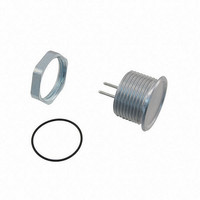
SWITCH PIEZO AL NAT M22 NO
Manufacturer
Schurter Inc
Type
Piezor
Series
PSEr
Datasheets
1.1241.3006.pdf
(23 pages)
2.1241.2353.pdf
(1 pages)
3.1241.2411.5.pdf
(14 pages)
4.1241.3008.pdf
(2 pages)
Specifications of 1241.3008
Switch Function
Off-Mom
Termination Style
PC Pin
Circuit
SPST-NO
Contact Rating @ Voltage
0.1A @ 42VAC/DC
Actuator Type
Flush Round Button
Mounting Type
Panel Mount
Contact Form
SPDT
Contact Rating
0.4 Amp at 20 Volts
Actuator
Button, Round
Mounting Style
Panel
Terminal Seal
Sealed
Contact Plating
Gold
Illumination
Not Illuminated
Body Length
13 mm
Body Shape
Round
Current Rating (max)
100 mAmps
Features
Ideal for use in hostile environment
Housing Material
Aluminum
Insulation Resistance
10 KOhms
Mounting Angle
Straight
Operating Force
3 N
Voltage Rating Ac
42 Volts
Voltage Rating Dc
60 Volts
Water / Moisture Rating
IP67
Application
For use in hostile environment
Color
Alu Natural
Current, Rating
0.1 mA
Ip Rating
IP67
Mounting Hole Size
22 mm
Operation
Piezo
Special Features
No moving parts
Standards
CE Certified
Temperature Rating
-40 to +85 °C °C
Termination
Terminal Pins
Thread Type
M22 x 1.5
Voltage, Rating
100 mA @ 60 VDC VDC
Contact Configuration
SPST-NO
Contact Voltage Ac Max
42V
Contact Voltage Dc Max
60V
Contact Current Max
100mA
Switch Terminals
Solder
Svhc
No SVHC (15-Dec-2010)
Rohs Compliant
Yes
Actuator / Cap Color
Natural
Lead Free Status / RoHS Status
Lead free / RoHS Compliant
Illumination Type, Color
-
Illumination Voltage (nominal)
-
Lead Free Status / Rohs Status
Lead free / RoHS Compliant
Other names
22ANAF-00000000-NO-S
486-1546
486-1546


SCHURTER GmbH
D – 79346 Endingen
www.schurter.com
Single or bi-colored ring illumination is possible for the PSE switches.
When equipped with two colors, it is possible to either switch between the colors or to achieve a
combination color, depending on the type of activation.
For example: Diodes of group 1 = red and diodes of group 2 = green
Terminal layout
Special type 5V upon request
When illuminating the PSE switch, either a single-color LED (2 pins) is used or a bi-colored LED (3
pins). If a single-color LED is used, cable No. 2 is not needed (see section 2.4 Switching Symbols:
Illumination – Point Illumination).
Switching between colors can be achieved by appropriate activation.
4 of 23
1.2
Page
Ring Illumination
Point Illumination
Functional Description: Illumination
Date of issue
19.05.2008
Only group 1 is activated
Only group 2 is activated
Both groups are activated at the same time
Red cable
Green cable
Black cable
White cable
see page 14 section 2.4 Switching Symbols Illumination
Author:
SHO
Changes that contribute to technical improvement are subject to alternations.
=
=
=
=
Date of change:
Supply voltage: red LEDs
Minus for all LEDs
Supply voltage: green LEDs
Switch contact
Changed by:
9738
Change No.
Ring has red illumination
Ring has green illumination
Ring has orange illumination
Datasheet No.
105.9524.200
Print date: 29/05/2008 08:44:00
Index
-
Related parts for 1241.3008
Image
Part Number
Description
Manufacturer
Datasheet
Request
R

Part Number:
Description:
MSM22 RI SF 10 A 250VAC GN
Manufacturer:
Schurter Inc
Datasheet:
Part Number:
Description:
LSH-Taster 6x6mm / 7,00mm-Blistergurt, taped and reeled
Manufacturer:
Schurter Inc
Part Number:
Description:
Fuse Drawer Quick Connect Snap-In
Manufacturer:
Schurter Inc
Datasheet:
Part Number:
Description:
Power Entry Module Filtered M 3 POS 250VAC 1A Switch/Fuse ST 1 Port
Manufacturer:
Schurter Inc
Datasheet:
Part Number:
Description:
Power Entry Module Filtered M 3 POS 250VAC 10A Switch/Fuse ST 1 Port
Manufacturer:
Schurter Inc
Datasheet:
Part Number:
Description:
Power Entry Module Filtered M 3 POS 250VAC 4A Switch/Fuse ST 1 Port
Manufacturer:
Schurter Inc
Datasheet:
Part Number:
Description:
Power Entry Module Filtered M 3 POS 250VAC 2A Switch/Fuse ST 1 Port
Manufacturer:
Schurter Inc
Datasheet:
Part Number:
Description:
6765 POWER ENTRY MODUL 10A 70C
Manufacturer:
Schurter Inc
Datasheet:
Part Number:
Description:
0102 APPLIANCE OUTLET FOR CABLE 10A 155
Manufacturer:
Schurter Inc