65021K206X Switchcraft Inc., 65021K206X Datasheet - Page 305
65021K206X
Manufacturer Part Number
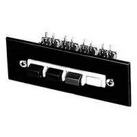
65021K206X
Description
SWITCH, MULTI-STATION, 2, DPDT, 3A SCREW
Manufacturer
Switchcraft Inc.
Series
65000r
Type
Standardr
Datasheet
1.65041K206X.pdf
(333 pages)
Specifications of 65021K206X
No. Of Stations
2
Contact Configuration
DPDT
Contact Current Max
3A
Contact Voltage Ac Nom
125V
Contact Voltage Dc Nom
125V
Switch Terminals
Solder Lug
Circuitry
DPDT
Rohs Information
Switchcraft RoHS Info.
Circuit
DPDT
Switch Function
-
Contact Rating @ Voltage
3A @ 125VAC
Actuator Type
Rectangular Button
Illumination Type, Color
-
Illumination Voltage (nominal)
-
Mounting Type
Panel Mount
Termination Style
Solder Lug
Lead Free Status / RoHS Status
Lead free / RoHS Compliant


300
w w w . s w i t c h c r a f t . c o m
SWITCHES
GENERAL PURPOSE STACK SWITCHES – COMPONENT SPECIFICATIONS
GENERAL PURPOSE STACK SWITCHES (continued)
GENERAL PURPOSE STACK SWITCHES – COMPONENT SPECIFICATIONS
STACK SWITCH COMPONENT SPECIFICATIONS
1. SPRINGS - Copper alloy in most standard gauge thickness-
es of .006" (0.15 mm), .008" (0.20 mm), .010" (0.25 mm), .012"
(0.30 mm), .016" (0.40 mm) and .020" (0.50 mm), a few designs
can be made up to .031" (.079 mm) thick. All or any contact
point hole can be provided; spring can be cut at any point.
2. BRACKETS - Standard brackets are detailed on drawing.
Tools are flexible so that various lengths from same width
stock can be provided.
3. LIFTERS OR PUSHERS - .125" (3.18 mm) and .188" (4.78
mm) diameter thermoplastic in various lengths staked into
one of the contact point holds provides tandem action
between blades or to serve as an actuator.
4. MOUNTING HARDWARE - Pressure plates (S1293 and
S2300) twin nuts (S1008 and S1431) and screws available for
mounting.
5. LEAF INSULATORS - Punched in same shape as springs
in .015" (0.38 mm) thickness of fish paper or mylar.
6. SPACERS - Rigid plastic is standard in thicknesses of .015"
(0.38 mm), .032" (0.81 mm), .051" (1.30 mm) and .062" (1.57
mm). Thickness of .093" (2.36 mm) is available for .375" (9.52
mm) mounting centers only. For longer surface creepage
paths, use both large and standard sized spacers. High tem-
perature insulation also available.
7. THERMOPLASTIC TUBING - .375" (9.52 mm) mounting
centers pass #5 screw. .250" (6.35 mm) mounting centers pass
#3 screw. .188" (4.78 mm) mounting centers pass #2 screw.
8. CAM FOLLOWERS - Two roller bracket designs (G1734
and G2298) available for springs .250" (6.35 mm) wide.
Copper alloy standard. Can be furnished in various diameters
and materials. Thermoplastic rollers also available.
9. CONTACTS - Welded cross bar contacts are commonly
used for cost savings. However, riveted contacts are available.
Size and material depend on circuit requirements (supply
complete details). For low level audio circuits, we suggest gold
alloy or palladium cross bar contacts. Springs can be
bifurcated (two contacts per spring).
TYPICAL STACK ASSEMBLY
* Please visit the product pages on our website for the most up-to-date product information
DIMENSIONS ARE FOR REFERENCE ONLY
HOW TO ORDER STACK SWITCHES
Careful consideration of the following suggestions will help
specify the most economical and expeditious approach to your
switching needs. On initial inquiry or order, supply the following
information:
1. Simple sketch or drawing. See “Typical Stack Assembly”
2. Current, voltage and type of switching load (resistive or
3. Frequency of operation; life requirements.
4. Details of actuator.
5. Maximum and minimum movement of actuator blade.
6. Any other important specifying details.
It is recommended that data indicated above be forwarded to
Switchcraft for comments and recommendations before finalizing
your design.
drawing. Give details checked that are available.
inductive).
1.
2.
3.
4.
5.
(mm)
Note: Contact your Switchcraft Representative for price and delivery
Inch
PHONE: 773 792 - 2700
® Registered trademark of Switchcraft, Inc.
6.
7.
8.
9.
Related parts for 65021K206X
Image
Part Number
Description
Manufacturer
Datasheet
Request
R


Part Number:
Description:
PHONE T-JACK PANEL .25" STD SGL
Manufacturer:
Switchcraft Inc.
Datasheet:

Part Number:
Description:
CONN JACK PANEL 96POS W/O JACK
Manufacturer:
Switchcraft Inc.
Datasheet:

Part Number:
Description:
CONN PHONE JACK 2COND 1/4" OPEN
Manufacturer:
Switchcraft Inc.
Datasheet:

Part Number:
Description:
CONN PLUG PHONE 1/4" 2POS RED
Manufacturer:
Switchcraft Inc.
Datasheet:

Part Number:
Description:
CONN JACK PHONE 1/4" 2POS W/HDWR
Manufacturer:
Switchcraft Inc.
Datasheet: