56SDP30-01-1-AJS Grayhill Inc, 56SDP30-01-1-AJS Datasheet - Page 2
56SDP30-01-1-AJS
Manufacturer Part Number
56SDP30-01-1-AJS
Description
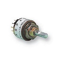
SWITCH, 1POLE, 12 POS
Manufacturer
Grayhill Inc
Datasheet
1.56D30-01-1-AJN.pdf
(4 pages)
Specifications of 56SDP30-01-1-AJS
No. Of Poles
1
No. Of Switch Positions
12
Contact Current Ac Max
200mA
Contact Current Dc Max
200mA
Contact Voltage Ac Max
115V
Contact Voltage Dc Max
30V
Svhc
No SVHC (15-Dec-2010)
Angle
30°
Behind
RoHS Compliant
Pole Throw Configuration
SP
Actuator Style
Shaft
Actuator Material
Zinc Die Cast
Current Rating (max)
0.2A
Illumination Type
Not Required
Ac Voltage Rating (max)
115VVAC
Dc Voltage Rating (max)
30VVDC
Contact Material
Brass
Contact Plating
Silver/Nickel
Product Height (mm)
28.07mm
Product Depth (mm)
12.7mm
Product Length (mm)
12.7mm
Mounting Style
Panel
Terminal Type
Solder Lug
Angle Of Throw
30°
Rohs Compliant
Yes
Lead Free Status / Rohs Status
Compliant


SPECIFICATIONS
Electrical Ratings
Chart shown for non-shorting (break before make)
contacts, resistive load.
One cycle is 360° rotation clockwise and 360°
return. The data for the curve was measured at
sea level, 25°C and 68% relative humidity with
the life limiting criteria which follows.
Contact Resistance: 100 milliohms maximum,
(15 milliohms initially).
Insulation Resistance: 10,000 Mohms
minimum between mutually insulated parts
(50,000 Mohms initially).
Voltage Breakdown: 600 Vac minimum
between mutually insulated parts at standard
atmospheric pressure.
Life Expectancy: As determined from the load-
life curve for the current to be switched. Contact
GRAYHILL for more information if any of the
following is true: the life limiting criteria are more
CIRCUIT DIAGRAMS AND REAR VIEWS: PC Mountable AND Solder Lug Terminals
POS. 1
POS. 1
300
200
100
36° TYP.
15°
30° TYP.
18°
0
0
COMMON LOCATION
FOR 1 POLE SWITCH
COMMON LOCATION
FOR 1 POLE SWITCH
115 Vac 0r 30 Vdc
CYCLES x 1000
10
Rear View
.366 ± .015
(9,30 ± 0,38)
DIA. CIRCLE
OF CENTERS
20
.340 ± .015
(8,64 ± 0,38) DIA.
CIRCLE OF CENTERS
COMMON LOCATION
FOR 2 POLE SWITCH
COMMON LOCATION
FOR 2 POLE SWITCH
.190 ± .015 (4,83 ± 0,38)
DIA. CIRCLE OF CENTERS
DIMENSION A
DIA. CIRCLE OF CENTERS
30
(PC MOUNT AND
SOLDER LUG)
Dimension
critical than those listed; longer operation is
required; a larger make and break current is
required; the operating environment includes
elevated temperatures or reduced pressures.
Contact Carry Rating: Switch will carry 6
amperes continuously with a maximum
contact temperature rise of 20°C.
Additional Characteristics
Contact Type and Forces: Shorting or non-
shorting wiping contacts with over 25 grams of
contact force.
Shaft Flat Orientation: Flat opposite contacting
position of pole number one (see circuit diagrams).
Terminals: Switches have the full circle of
terminals, regardless of number of active positions.
Stop Strength: 7.5 lb-in. minimum
Rotational Torque: 3.5 to 9 oz-in. (21-53 mN-
m), depending on the number of poles.
Bushing Mounting: Required for switches with
stops, and recommended for switches without
stops.
Meets MIL-S-3786 for:
High and medium shock; Vibration (10 to 2,000
Hz); Thermal shock (-65° to 85 ° C); Salt spray;
Explosion; Stop strength (7.5 in-lbs. minimum
(.85 N-m); Terminal strength; Sealed styles
withstand water pressure of 15 PSI minimum
(103 KPa) without leakage.
A
POS. 1
30° TYP.
15°
PC Mount
Terminals
.184 ± .015
(4,67 ± 0,38)
Solder Lug
Terminals
.126 ± .015
(3,20 ± 0,38)
Circuit as Viewed From Shaft End
.366 ± .015
(9,30 ± 0,38)
DIA. CIRCLE
OF CENTERS
.190 ± .015 (4,83 ± 0,38)
DIA. CIRCLE OF CENTERS
(PC MOUNT AND
SOLDER LUG)
6
5
7
6
8
5
4
7
TWO POLES
ONE POLE
4
9
C1
8
3
C2
10
3
Materials and Finishes
Housing: Zinc die cast, zinc-plated with chromate
treatment.
Mounting Nut: Brass, zinc-plated with chromate
treatment.
Lockwasher: Spring steel, zinc-plated with
chromate treatment.
Panel Seal: Silicone rubber
Shaft and Stop Arm: Zinc die cast, zinc-plated
with chromate treatment.
Retaining Ring: 302 Stainless steel, passivated
Shaft Seal: Silicone rubber
Stop Pins: 303 Stainless steel, passivated
Detent Rotor: Molded thermoplastic
Detent Spring: Tinned music wire
Detent Balls: Steel, nickel-plated
Contact Spring: Stainless steel, passivated
Rotor Contact: Brass, silver over nickel plate
Common Ring: Brass, gold over silver over
nickel plate
Terminals: Brass, gold over silver over nickel
plate
Switch Base: Molded thermoset plastic
Mounting Hardware: One mounting nut .089"
thick by .375" across flats and one internal tooth
lockwasher are supplied with the switch.
9
11
2
2
10
12
1
1
6
5
7
6
7
6
8
8
5
5
4
FOUR POLES
7
TWO POLES
ONE POLE
C2
9
4
9
4
C1
C3
8
3
C1
C2
10
10
3
3
C4
11
9
2
2
11
2
12
10
1
12
1
1
36° Angle
of Throw
30° Angle
of Throw
Related parts for 56SDP30-01-1-AJS
Image
Part Number
Description
Manufacturer
Datasheet
Request
R

Part Number:
Description:
SWITCH, ROTARY, SP12T, 200mA, 115V
Manufacturer:
Grayhill Inc
Datasheet:
Part Number:
Description:
SWITCH, ROTARY, DP6T, 200mA, 115V
Manufacturer:
Grayhill Inc
Datasheet:

Part Number:
Description:
SWITCH, 2POLE, 6 POS
Manufacturer:
Grayhill Inc
Datasheet:

Part Number:
Description:
Rotary Switch, Shaft/panel Seal, Adjustable Stop, PC Mount, 30°
Manufacturer:
Grayhill Inc
Datasheet:
Part Number:
Description:
Rotary Switch, Shaft/panel Seal, Adjustable Stop, PC Mount, 30°
Manufacturer:
Grayhill Inc
Part Number:
Description:
Rotary Switch, Shaft/panel Seal, Adjustable Stop, PC Mount, 30°
Manufacturer:
Grayhill Inc
Datasheet:
Part Number:
Description:
Rotary Switch, Shaft/panel Seal, Adjustable Stop, PC Mount, 30°
Manufacturer:
Grayhill Inc
Part Number:
Description:
Rotary Switch, Shaft/panel Seal, Adjustable Stop, PC Mount, 30°
Manufacturer:
Grayhill Inc
Part Number:
Description:
Rotary Switch, Shaft/panel Seal, Adjustable Stop, PC Mount, 30°
Manufacturer:
Grayhill Inc
Part Number:
Description:
Encoder; 32pos; custom switching; sealed; continous rotation;
Manufacturer:
Grayhill Inc
Part Number:
Description:
50EPT90-01-1-04N-C SINGLE DECK ROTARY 0.5(12.7mm)DIA,200mA,Continuous
Manufacturer:
Grayhill Inc
Part Number:
Description:
Rotary Switch seal adj.stop 36� 1deck 1pol/deck 56BSD36-01PAJN -bulk
Manufacturer:
Grayhill Inc
Part Number:
Description:
Rotary Switch, Screwdriver slot shaft, shaft/panel seal, PC mount, 30°
Manufacturer:
Grayhill Inc
Part Number:
Description:
Encoder MODIFIED SPECIAL VERSION OF GRH'S 60A18-4-040C
Manufacturer:
Grayhill Inc