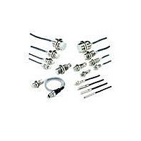
E2E-X10MF1-M1 Omron, E2E-X10MF1-M1 Datasheet - Page 42

E2E-X10MF1-M1
Manufacturer Part Number
E2E-X10MF1-M1
Description
PROXIMITY SENSOR
Manufacturer
Omron
Series
E2Er
Specifications of E2E-X10MF1-M1
Rohs Compliant
YES
Maximum Operating Temperature
+ 85 C
Supply Voltage
30 V
Output Voltage
2 V
Operating Supply Voltage
12 V to 24 V
Minimum Operating Temperature
- 40 C
Maximum Output Current
200 mA
Features
High visibility indicator
Sensing Distance
10 mm
Sensor Type
Inductive
Sensing Object
Metallic
Response Frequency
200Hz
Material - Body
Nickel-Plated Brass
Shielding
Unshielded
Voltage - Supply
10 V ~ 30 V
Output Type
PNP-NO
Terminal Type
Connector
Package / Case
Cylinder, Threaded - M18
Sensor Input
Inductive
Sensing Range
10mm
Supply Voltage Range Dc
12V To 24V
Lead Free Status / RoHS Status
Lead free / RoHS Compliant
Lead Free Status / RoHS Status
Lead free / RoHS Compliant
42
M12 Connector Models
(Shielded)
Fig. 18: E2E-X2D@-M1(G)
Fig. 20: E2E-X3D@-M1(G)
Fig. 22: E2E-X2Y@-M1
Fig. 24: E2E-X7D@-M1(G)/E2E-X5E@-M1/F@-M1
Fig. 26: E2E-X10D@-M1(G)/E2E-X10E@-M1/F@-M1
Note: D Models: Operation indicator (red), setting indicator (green)
Note: D Models: Operation indicator (red), setting indicator (green)
Note: D Models: Operation indicator (red), setting indicator (green)
Note: D Models: Operation indicator (red), setting indicator (green)
E, F Model: Operation indicator (red)
E, F, Y Model: Operation indicator (red)
E, F Model: Operation indicator (red)
E, F, Y Model: Operation indicator (red)
E2E-X1R5E@-M1/F@-M1
E2E-X2E@-M1/F@-M1
E2E-X5Y@-M1
E2E-X10Y@-M1
21 dia.
21 dia.
15 dia.
42 dia.
29 dia.
17
17
13
36
24
E2E/E2E2
M12 × 1
M12 × 1
M8 × 1
M18 × 1
M30 × 1.5
Toothed washer
3
4
4
26
33
30
Toothed washer
38
Toothed washer
Toothed washer
4
Two clamping nuts
48
43
5
Two clamping nuts
Two clamping nuts
8
38
53
10
Cylindrical Proximity Sensor
Toothed washer
10
Indicator (See note.)
53
Toothed washer
43
Two clamping nuts
Indicator (See note.)
10
Two clamping nuts
Operating indicator (red)
58
M12 × 1
M12 × 1
10
Indicator (See note.)
M12 × 1
M12 × 1
Indicator (See note.)
M12 × 1
M12 Connector Models
(Unshielded)
Fig. 19: E2E-X4MD@-M1(G)
Fig. 21: E2E-X8MD@-M1(G)
Fig. 23: E2E-X5MY@-M1
Fig. 25: E2E-X14MD@-M1(G)/E2E-X10ME@-M1/F@-M1
Fig. 27: E2E-X20MD@-M1(G)/E2E-X18ME@-M1/F@-M1
Note: D Models: Operation indicator (red), setting indicator (green)
Note: D Models: Operation indicator (red), setting indicator (green)
Note: D Models: Operation indicator (red), setting indicator (green)
Note: D Models: Operation indicator (red), setting indicator (green)
E, F, Y Model: Operation indicator (red)
E, F, Y Model: Operation indicator (red)
E, F Model: Operation indicator (red)
E, F Model: Operation indicator (red)
42 dia.
E2E-X2ME@-M1/F@-M1
E2E-X5ME@-M1/F@-M1
E2E-X10MY@-M1
E2E-X18MY@-M1
21 dia.
21 dia.
29 dia.
15 dia.
36
17
17
13
24
6.1 dia.
9 dia.
9 dia.
14.8 dia.
M8 × 1
M12 × 1
M12 × 1
26.8 dia.
6
7
7
M18 × 1
M30 × 1.5
3
26
4
10
30
13
4
33
38
43
8
Toothed washer
Two clamping nuts
Toothed washer
48
Toothed washer
4
53
10
Two clamping nuts
38
Indicator (See note.)
Two clamping nuts
43
5
10
Toothed washer
53
Indicator (See note.)
Two clamping nuts
58
Toothed washer
10
Operation indicator (red)
M12 × 1
Two clamping nuts
10
M12 × 1
Indicator (See note.)
M12 × 1
Indicator (See note).
M12 × 1
M12 × 1


