44UA30-02-2-04N Grayhill Inc, 44UA30-02-2-04N Datasheet
44UA30-02-2-04N
Specifications of 44UA30-02-2-04N


Related parts for 44UA30-02-2-04N


44UA30-02-2-04N Summary of contents
Page 1
... KEYWAY SEE NOTE NON-TURN TAB .125 ± .003 (3,18 ± 0,08) WIDE BY .031 ± .003 (0,79 ± 0,08) THICK Note: Common location for a single pole per deck switch. For common location on multi-pole switches, see circuit diagrams. No. Dimension B of Dimension Style Decks ...
Page 2
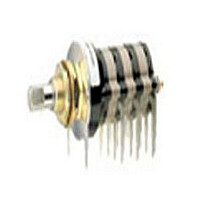
... ONE POLE 5 6 Series 60° Angle 1 of Throw 3 2 ONE POLE 4 Series 90° Angle 1 of Throw 2 ONE POLE Grayhill, Inc. • 561 Hillgrove Avenue • LaGrange, Illinois Multi-Deck Rotary Switches Note: All common terminals are located above base terminals as shown TWO POLE ...
Page 3
... The Series 42/44 Styles, which include the letter "S" with the exception of style "HS", are watertight sealed to the mounting panel by utilizing the panel seal kit. These switches are built with a front plate that does not have a non-turn tab. The panel seal kit consists of a grooved hex nut, a keyed washer and a keyed panel seal ...
Page 4
... SERIES 43 SERIES 54 1" Diameter, 1 Amp, Concentric Shafts FEATURES • Two Switches in the Panel Space of a Single Shaft Rotary • Military Qualified Versions MIL-3786/04 • Choice of 10 Positions (Series 43 Positions (Series 54) DIMENSIONS In inches (and millimeters) Standard Style and Military Qualified 1.162 (29,51) DIA. ...
Page 5
... Plated brass spacers for ease of positioning mounting plate driving assembly are available on special request (sold only with switches). The use of spacers is recommended for other than " prototype requirements. When ordering switches with spacers, give full details regarding special length, potentiometer being used, etc. ...
Page 6
... NON-TURN TAB .125 ± .003 (3,18 ± 0,08) WIDE BY .031 ± .003 (0,79 ± 0,08) THICK Note: Common locations for a single pole per deck switch. For common location on multiple switches, see circuit diagram. Number Approximate of Dimension Weight Decks ...
Page 7
... All Qualified Switches Complete electrical ratings and characteristics for all of these qualified switches are listed on the Rating based on the following criteria: Overload: 50 operations at 150% rated AC load Endurance: 6000 operations at the rated load ...
Page 8
... Vdc resistive; 25 milliamperes, 28 Vdc inductive (2.8 henries); 20 milliamperes, 115 Vac resistive. When tested to these loads and conditions the style M, H and HS switches meet the following life limiting or failure criteria after 25,000 cycles in accordance with MIL-S-3786. Contact Resistance: 50 milliohms maximum Insulation Resistance: 1,000 megaohms ...
Page 9
... For Adjustable Stop (with the letter D), use AJ instead of number of positions when ordering. 2 For 45°, 60° or 90° throws in Series 54 switches of these styles, see Standard Options. 3 For single pole switches with the maximum positions per pole, continuous rotation is possible. Specify fixed stop or continuous rotation when ordering single shaft switches ...
Page 10
... Poles Per Deck Number of Decks Style * All rotary switches that are required to have military designated markings and testing adhering to MIL-3786 are to be ordered by specifying the military part number identified on the appropriate slash sheet. Available from your local Grayhill Distributor Grayhill, Inc. • 561 Hillgrove Avenue • LaGrange, Illinois Multi-Deck Rotary Switches bushing to the panel ...