EVQQ2F03W Panasonic, EVQQ2F03W Datasheet - Page 10
EVQQ2F03W
Manufacturer Part Number
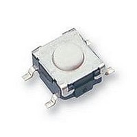
EVQQ2F03W
Description
SWITCH, SPNO, SMD
Manufacturer
Panasonic
Datasheet
1.EVQQ2F03W.pdf
(13 pages)
Specifications of EVQQ2F03W
Contact Configuration
SPST-NO
Operating Force
1N
Contact Voltage Dc Nom
15V
Contact Current Max
20mA
Actuation Type
Top
Switch Terminals
Surface Mount
Svhc
No SVHC (18-Jun-2010)
Actuator / Cap Colour
White
Lead Free Status / RoHS Status
Lead free / RoHS Compliant
Available stocks
Company
Part Number
Manufacturer
Quantity
Price
Company:

Part Number:
EVQQ2F03W
Manufacturer:
PANASONIC
Quantity:
30 000


■
When using our Light Touch Switches, please ob serve
the following items (“prohibited items”) and be
cau tious of the following in order to prevent dan ger ous
accidents and deterioration of performance.
1. Notes on soldering conditions
When performing solder dipping, check the soldering
conditions according to the “Product Specifi cation
for Information,” because the conditions vary with the
prod uct. Do not wash the switch after solder dipping
be cause fl ux may enter the switch, resulting in contact
failure. Avoid use of jumper cables near the switches
be cause fl ux may attach to them.
1. Control the liquid level so that fl ux does not enter
2. When performing manual soldering, perform it at a
3. Do not apply a load to the switch lever after sol der ing.
4. For refl ow soldering
5. When a board with double-sided through holes is
2. Notes on design of a set
1. For switch mounting holes, refer to the “Rec om mend ed
2. For shapes of operating parts in a set, refer to
Design and specifi cations are each subject to change without notice. Ask factory for the current technical specifi cations before purchase and/or use.
Should a safety concern arise regarding this product, please be sure to contact us immediately.
the switch from the top.
temperature of 280 °C within 3 seconds.
When performing refl ow soldering using a hot-air
oven or an infrared oven, observe the following
con di tions. Since the temperature applied to a
switch and its ter mi nals varies with the type and
size of the PWB and the mounting density of the
parts, suf fi cient ly check the conditions in advance.
used, do not make through holes immediately under
the switch case. Otherwise, the switch case may fuse.
Notes:
● Measure temperature profi le at the part surface.
● Do not perform refl ow soldering more than twice.
PWB piercing plan” as described in “Di men sions.”
rec om mend ed shapes described in “ Product
Specifi cations for Information.”
Application Notes
Temperature
rising part
230
220
210
200
1
1Temperature rising part : Ordinary temperature to
2Pre-heating part: 150 to 180 °C, 60 to 120 s.
3Temperature rising part : Pre-heating part to 230 °C,
4Main heating part: Rater to the figure below.
5Cooling part: Between 230 to 100 °C, 2 to 4 °C/s
6Peak Temperature: 260 °C max.
30 to 50 s.
0
Pre-heating part: 30 to 60 s.
Product reflow specified condition
Pre-heating part
Time (s) at 200 °C or more
2
(Main heating part)
20
230 °C
Time
Temperature
rising part
3
Main heating
Peak Temperature
40
4
Cooling part
5
60
6
3. Other prohibited items and notes
1. Take care not to apply excessive load to a switch.
2. Suffi ciently check any generation of corrosive gas
3. To prevent contact failure due to foreign matter
4. Prohibited items and notes on storage con di tions
Do not store the switches under high temperatures
and/or high humidity, or in a location where cor ro sive
gas may be generated. Store the switches at room
tem per a ture and room humidity in a packed con di tion.
Use them within a maximum of 6 months af ter de liv ery.
Check the date of manufacture on the pack age box
and ap ply the “fi rst-in -fi rst- out” rule. If unpacked
switch es must be stored as inventory, store them in a
poly eth yl ene bag to keep out air.
5. Prohibited items on fi re and smoking
1. Absolutely avoid use of a switch beyond its rated
2. The grade of nonfl ammability for resin used in Light
6. For use in equipment for which safety re quest ed
7. For actual use, be sure to refer to “Product
Doing so may cause terminal deformation, contact
fail ure, and/or malfunction.
from the components in a set under actual oper ating
conditions. Corrosive gas may cause contact failure
and corrosive stress cracking of metal.
(such as chips of a PWB and fl ux) entering a
switch, take care when handling a PWB after mounting.
Do not stack the PWB’s.
range because doing so may cause a fi re.
If misuse or abnormal use may result in conditions
in which the switch is used out of its rated range,
take proper measures such as current interruption
using a protective circuit.
Touch Switches is “94HB”, which is based on UL94
Standards (fl ammability test for plastic ma te ri als).
Pro hib it use in a location where a spread ing fi re
may be generated or prepare against a spreading
fi re.
Although care is taken to ensure switch quality,
vari a tion of contact resistance (increase), short
cir cuits, open circuits, and temperature rise are
some prob lems that might be generated.
To de sign a set which places maximum em pha sis
on safety, review the affect of any single fault of
a switch in advance and perform virtually fail-safe
design to ensure maximum safety by:
1. preparing a protective circuit or a protective
2. preparing a redundant circuit to improve system
Spec i fi ca tions for Information.”
device to improve system safety, and
safe ty so that the single fault of a switch does
not cause a dangerous situation.
Light Touch Switches
Feb. 2006
Related parts for EVQQ2F03W
Image
Part Number
Description
Manufacturer
Datasheet
Request
R

Part Number:
Description:
SWITCH LT 6MM 260GF H=2.5MM SMD
Manufacturer:
Panasonic - ECG
Datasheet:

Part Number:
Description:
SWITCH LT 6MM 260GF H=3.1MM SMD
Manufacturer:
Panasonic - ECG
Datasheet:
Part Number:
Description:
SWITCH LT 6MM 130GF H=3.1MM SMD
Manufacturer:
Panasonic - ECG
Datasheet:
Part Number:
Description:
SWITCH LT 6MM 160GF H=2.5MM SMD
Manufacturer:
Panasonic - ECG
Datasheet:
Part Number:
Description:
SWITCH LT 6MM 50GF H=3.1MM SMD
Manufacturer:
Panasonic - ECG
Datasheet:
Part Number:
Description:
SWITCH LT 6MM 100GF H=2.5MM SMD
Manufacturer:
Panasonic - ECG
Datasheet:
Part Number:
Description:
SWITCH LT 6MM 350GF H=3.1MM SMD
Manufacturer:
Panasonic - ECG
Datasheet:
Part Number:
Description:
SWITCH LT 6MM 100GF H=3.1MM SMD
Manufacturer:
Panasonic - ECG
Datasheet:

Part Number:
Description:
SWITCH LT 6MM 260GF H=2MM SMD
Manufacturer:
Panasonic - ECG
Datasheet:
Part Number:
Description:
SWITCH LT 6MM 50GF H=3.1MM SMD
Manufacturer:
Panasonic - ECG
Datasheet:

Part Number:
Description:
Color CCD Linear Image Sensor with 1024 Pixels for R and B Colors/2048 Pixels for G Color
Manufacturer:
Panasonic
Datasheet:
Part Number:
Description:
2048-Bit CCD Linear Image Sensor
Manufacturer:
Panasonic
Datasheet:
Part Number:
Description:
2592-Bit CCD Linear Image Sensor
Manufacturer:
Panasonic
Datasheet:
Part Number:
Description:
2048-Bit High-Responsivity CCD Linear Image Sensor with Internal Clock Driver
Manufacturer:
Panasonic
Datasheet: