G6K-2F 5DC Omron, G6K-2F 5DC Datasheet
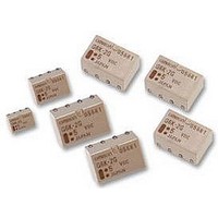
G6K-2F 5DC
Specifications of G6K-2F 5DC


Related parts for G6K-2F 5DC


G6K-2F 5DC Summary of contents
Page 1
... Note: 1. When ordering, add the rated coil voltage to the model number. Example: G6K-2F 12 VDC Rated coil voltage 2. When ordering tape packing, add “-TR” to the model number. Example: G6K-2F-TR 12 VDC Tape packing Be sure since “-TR” is not part of the relay model number not marked on the relay case. Model Number Legend ...
Page 2
... Note: 1. The rated current and coil resistance are measured at a coil temperature of 23#C with a tolerance of $10%. 2. The operating characteristics are measured at a coil temperature of 23#C. 3. The maximum voltage is the highest voltage that can be imposed on the relay coil instantaneously. Single-side Stable Models (Bellcore Version) G6K-2F-Y, G6K-2G-Y, G6K-2P-Y Rated voltage Rated current Coil resistance ...
Page 3
... Approx. 100 mW Resistive load 0 125 VAC VDC 1 A 125 VAC, 60 VDC 1 A Single-side stable models (double-pole) G6K-2F, G6K-2G, G6K-2P G6K-2F-Y, G6K-2G-Y, G6K-2P-Y 2,500 !s), 1,500 V (10 x 160 !s) 2 (approx. 100G) 2 (approx. 75G) 100,000 operations min. (with a rated load at 1,800 operations/hour) ...
Page 4
... Ambient temperature (#C) Ambient Temperature vs. Must Set or Must Reset Voltage G6KU-2G (F/P)-Y Max. estimated value Ambient temperature (#C) Electrical Life Expectancy (Contact Resistance) (see note) G6K-2G (F/P), G6K-2G (F/P)-Y NO Sample: G6K-2G contact Number of Relays Test conditions resistive load contact at 30 VDC with an operation rate of 50% ...
Page 5
... Sample: G6K-2G Must operate voltage Number of Relays: 10 Must release voltage External magnetic field (A/m) High-frequency Characteristics (Insertion Loss) G6K-2G (F/P), G6K-2G (F/P)-Y (Average value) Sample: G6K-2G Number of Relays: 10 Frequency (MHz) G6K Mutual Magnetic Interference G6K-2G (F/P), G6K-2G (F/P)-Y Must operate voltage ...
Page 6
... Note: Each value has a tolerance of $0.3 mm. G6K-2P Note: Each value has a tolerance of $0.3 mm. 6 Must Operate and Must Release Bounce Time Distribution (see note) G6K-2G (F/P) , G6K-2G (F/P)-Y Must operate bounce time Must release bounce time Sample: G6K-2G Number of Relays: 50 Time (ms) Mounting Dimensions (Top View) Tolerance: $0 ...
Page 7
... G6K-2G-Y Note: Each value has a tolerance of $0.3 mm. G6K-2P-Y Note: Each value has a tolerance of $0.3 mm. G6KU-2F-Y Note: Each value has a tolerance of $0.3 mm. G6KU-2G-Y Note: Each value has a tolerance of $0.3 mm. G6KU-2P-Y Note: Each value has a tolerance of $0.3 mm. Mounting Dimensions (Top View) Terminal Arrangement/ Internal Connections Tolerance: $0 ...
Page 8
... Industrial Association of Japan)) Reel type: RPM-16D (EIAJ) Relays per Reel: 900 1. Direction of Relay Insertion Top tape (cover tape) Carrier tape Emboss tape 2. Reel Dimensions 8 Stopper (green) 3. Carrier Tape Dimensions Pulling direction G6K-2F, G6K-2F-Y, G6KU-2F-Y Orientation mark Pulling direction G6K-2G, G6K-2G-Y, G6KU-2G-Y G6K ...
Page 9
... Land Visually check that the Relay is properly soldered. Approved Standards UL approval: UL1950 (File No. E41515) CSA approval: C22.2 No. 950 (File No. LR24825) Contact form Coil rating DPDT G6K-2G(F/P): G6K(U)-2G(F/P)- VDC Excessive amount of solder Contact rating VDC VDC 0 VDC 0 125 VAC G6K Number of test operations ...
Page 10
... G6K Precautions For general precautions, refer to the PCB Relays Catalog (X033). Familiarize yourself with the precautions and glossary before using the G6K. Correct Use Handling Leave the Relay unpacked until mounting it. Soldering Solder: JIS Z3282, H63A Soldering temperature: Approx. 250#C (260#C if the DWS method is used) Soldering time: Approx ...