G6K-2P 12DC Omron, G6K-2P 12DC Datasheet - Page 10
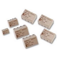
G6K-2P 12DC
Manufacturer Part Number
G6K-2P 12DC
Description
RELAY, PCB, DPCO, 12VDC
Manufacturer
Omron
Datasheet
1.G6K-2F_24DC.pdf
(10 pages)
Specifications of G6K-2P 12DC
Coil Type
DC Coil, Monostable
Contact Current Max
1A
Contact Voltage Ac Nom
125V
Contact Voltage Dc Nom
30V
Coil Voltage Vdc Nom
12V
Coil Current
9.1mA
Coil Resistance
1.315kohm
Relay Mounting
PC
Contact Configuration
DPDT
Rohs Compliant
Yes
Lead Free Status / RoHS Status
Lead free / RoHS Compliant


G6K
Precautions
For general precautions, refer to the PCB Relays Catalog (X033).
Familiarize yourself with the precautions and glossary before using
the G6K.
Correct Use
Handling
Leave the Relay unpacked until mounting it.
Soldering
Solder: JIS Z3282, H63A
Soldering temperature: Approx. 250#C (260#C if the DWS method is
used)
Soldering time: Approx. 5 s max. (approx. 2 s for the first time and
approx. 3 s for the second time if the DWS method is used)
Be sure to make a molten solder level adjustment so that the solder
will not overflow on the PCB.
Claw Securing Force During Automatic Mounting
During automatic insertion of Relays, make sure to set the securing
force of each claw to the following so that the Relays characteristics
will be maintained.
Environmental Conditions During Operation, Storage, and
Transportation
Protect the Relay from direct sunlight and keep the Relay under nor-
mal temperature, humidity, and pressure.
If the Relay is stored for a long time in an adverse environment with
high temperature, high humidity, organic gases, or sulfide gases,
sulfide or oxide films will form on the contact surfaces. These films
may result in unstable contact, contact problems, or functional prob-
lems. Therefore, operate, store, or transport the product under spe-
cified environmental conditions.
Latching Relay Mounting
Make sure that the vibration or shock that is generated from other
devices, such as relays in operation, on the same panel and im-
posed on the Latching Relay does not exceed the rated value,
otherwise the Latching Relay that has been set may be reset or vice
versa. The Latching Relay is reset before shipping. If excessive
vibration or shock is imposed, however, the Latching Relay may be
set accidentally. Be sure to apply a reset signal before use.
10
Cat. No. K106-E1-3A
ALL DIMENSIONS SHOWN ARE IN MILLIMETERS.
To convert millimeters into inches, multiply by 0.03937. To convert grams into ounces, multiply by 0.03527.
Direction A: 1.96 N
Direction B: 4.90 N
Direction C: 1.96 N
Maximum Allowable Voltage
The maximum allowable voltage of the coil can be obtained from the
coil temperature increase and the heat-resisting temperature of coil
insulating sheath material. (Exceeding the heat-resisting tempera-
ture may result in burning or short-circuiting.) The maximum allow-
able voltage also involves important restrictions which include the
following:
%
%
%
%
Therefore, be sure to use the maximum allowable voltage beyond
the value specified in the catalog.
As a rule, the rated voltage must be applied to the coil. A voltage ex-
ceeding the rated value, however, can be applied to the coil pro-
vided that the voltage is less than the maximum allowable voltage. It
must be noted that continuous voltage application to the coil will
cause a coil temperature increase thus affecting characteristics
such as electrical life and resulting in the deterioration of coil insula-
tion.
Coating
The Relay mounted on the PCB may be coated or washed but do
not apply silicone coating or detergent containing silicone, other-
wise the silicone coating or detergent may remain on the surface of
the Relay.
PCB Mounting
If two or more Relays are closely mounted with the long sides of the
Relays facing each other and soldering is performed with infrared
radiation, the solder may not be properly exposed to the infrared
rays. Be sure to keep the proper distance between adjacent Relays
as shown below.
Two or more Relays may be closely mounted with the short sides of
the Relays facing each other.
Must not cause thermal changes in or deterioration of the
insulating material.
Must not cause damage to other control devices.
Must not cause any harmful effect on people.
Must not cause fire.
G6K-2G
G6K-2F
2 mm min.
2.7 mm min.
G6K
Related parts for G6K-2P 12DC
Image
Part Number
Description
Manufacturer
Datasheet
Request
R

Part Number:
Description:
RELAY TELCOM DPDT 1A 24VDC PCB
Manufacturer:
Omron
Datasheet:

Part Number:
Description:
LOW SIGNAL RELAY
Manufacturer:
Omron
Datasheet:
Part Number:
Description:
LOW SIGNAL RELAY
Manufacturer:
Omron
Datasheet:
Part Number:
Description:
RELAY PC MNT DPDT 1A 3VDC
Manufacturer:
Omron
Datasheet:
Part Number:
Description:
RELAY TELCOM DPDT 1A 12VDC PCB
Manufacturer:
Omron
Datasheet:
Part Number:
Description:
RELAY PC MNT DPDT 1A 5V
Manufacturer:
Omron
Datasheet:
Part Number:
Description:
RELAY TELCOM DPDT 1A 5VDC PCB
Manufacturer:
Omron
Datasheet:
Part Number:
Description:
RELAY TELCOM DPDT 1A 4.5VDC PCB
Manufacturer:
Omron
Datasheet:
Part Number:
Description:
RELAY PC MNT DPDT 1A 4.5V
Manufacturer:
Omron
Datasheet:
Part Number:
Description:
RELAY PC MNT DPDT 1A 12V
Manufacturer:
Omron
Datasheet:
Part Number:
Description:
RELAY PC MNT DPDT 1A 24V
Manufacturer:
Omron
Datasheet:

Part Number:
Description:
LOW SIGNAL RELAY
Manufacturer:
Omron
Datasheet:
Part Number:
Description:
LOW SIGNAL RELAY
Manufacturer:
Omron
Datasheet:
Part Number:
Description:
LOW SIGNAL RELAY
Manufacturer:
Omron
Datasheet:

Part Number:
Description:
LOW SIGNAL RELAY
Manufacturer:
Omron
Datasheet: