LH1514AB Vishay, LH1514AB Datasheet
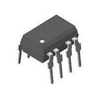
IC,Normally-Open PC-Mount Solid-State Relay,2-CHANNEL,DIP

LH1514AB

Manufacturer Part Number
LH1514AB
Description
IC,Normally-Open PC-Mount Solid-State Relay,2-CHANNEL,DIP
Manufacturer
Vishay
Datasheet

Specifications of LH1514AB

Load Voltage Rating
15 V
Load Current Rating
0.15 A
Contact Form
1 Form 2A
Output Device
MOSFET
Maximum Operating Temperature
+ 85 C
Minimum Operating Temperature
- 40 C
Package / Case
PDIP-8
Output Type
AC, DC
Mounting Style
Through Hole
Case Color
Black
Relay Type
Solid State
Lead Free Status / RoHS Status
Lead free / RoHS Compliant
Lead Free Status / RoHS Status
Lead free / RoHS Compliant, Lead free / RoHS Compliant
FEATURES
• Load Voltage, 15 V
• Load Current, 150 mA
• Switching Capability up to 50 MHz
• Blocking Capability Dependent upon
• Low and Typical R
• 1.0 ms Actuation Time
• Low Power Consumption
• 3750 V
• Balanced Switching
• Linear AC/DC Operation
• Clean, Bounce-free Switching
• Surface-mountable
AGENCY APPROVALS
• UL – File No. E52744
• CSA – Certification 093751
• VDE 0884 Approval
APPLICATIONS
• Protection Switching (T1 sparing)
• Transmission Switching
• Instrumentation
• See Application Note
Part Identification
Document Number: 83814
Revision 17-August-01
Part Number
LH1514AB
LH1514AAC
LH1514AACTR
Signal dv/dt
– Digital Access Cross Connects
– D-type Channel Breaks
– Intraoffice Data Routing
– T1 Multiplexing
– DSO (64 Kbits/s)
– DS1 (1.544 Mbits/s)
– E1, DS1A (2.048 Mbits/s)
– DS1C (3.152 Mbits/s)
– DS2 (6.312 Mbits/s)
– Scanners
– Testers
– Measurement Equipment
RMS
I/O Isolation
ON
5.0 Ω
Description
8-pin DIP, Tubes
8-pin SMD, Gullwing, Tubes
8-pin SMD, Gullwing, Tape and
Reel
DESCRIPTION
The LH1514 is a DPST normally open (2 Form A) SSR that can be
used in balanced high-frequency applications like T1 switching. With
its low ON-resistance and high actuation rate, the LH1514 is also very
attractive as a general-purpose 2 Form A SSR for balanced signals.
The relays are constructed using a GaAlAs LED for actuation control
and an integrated monolithic die for the switch output. The die, fabri-
cated in a dielectrically isolated Smart Power BiCMOS, is comprised
of a photodiode array, switch control circuitry, and NMOS switches.
In balanced switching applications, internal circuitry shunts high-fre-
quency signals between two poles when the SSR is off. This bal-
anced T termination technique provides high isolation for the load.
Package Dimensions in Inches (mm)
.045 (1.14)
.030 (0.76)
.050 (1.27)
typ.
SMD
.268 (6.81)
.255 (6.48)
DIP
.022 (.56)
.018 (.46)
(1.27)
.050
4° typ.
typ.
.390 (9.91)
.379 (9.63)
.045 (1.14)
.030 (0.78)
4
5
.390 (9.91)
.379 (9.63)
3
6
.100 (2.54) typ.
.100 (2.54)
2
.031 (.79)
7
.268 (6.81)
.255 (6.48)
typ.
typ.
.150 (3.81)
.130 (3.30)
.008 (.25)
.004 (.10)
.031 (0.79)
1
8
Pin one I.D.
LH1514AB/AAC/AACTR
.035 (.89)
.020 (.51)
pin one ID
.150 (3.81)
.130 (3.30)
.040 (1.02)
.020 (.51)
Radius
S1
8
1
.300 (7.62)
3°–9°
S1'
2
.012 (.30)
.008 (.20)
7
Solid State Relay
.395 (10.03)
.375 (9.52)
.312 (7.80)
.298 (7.52)
typ.
10°
High Frequency
S2
(8.00)
.315
typ.
6
3
10°
S2'
5
4
www.vishay.com
2 Form A
S1
S2
3
.250 (6.35)
.230 (5.84)
.130 (3.30)
.110 (2.79)
.010
(2.54)
typ.
°
to 7
°
3–72
S1'
S2'

Related parts for LH1514AB

LH1514AB Summary of contents

Page 1

... See Application Note Part Identification Part Number Description LH1514AB 8-pin DIP, Tubes LH1514AAC 8-pin SMD, Gullwing, Tubes LH1514AACTR 8-pin SMD, Gullwing, Tape and Reel Document Number: 83814 Revision 17-August-01 LH1514AB/AAC/AACTR Package Dimensions in Inches (mm) DIP pin one .268 (6.81) .255 (6.48 ...

Page 2

... I =0 mA, F ± –12 –6 V 20x10 1.0x10 µ A 1.0 5 Pins 7, 8 Pins 5, 6 Gnd µ A 2.0 50 Pins 7, 8 Pins 5, 6 Gnd 20 — mA — mA — =10 mA, F 0.4 1 =10 mA, F 0.6 1 =10 mA, F RMS I =± =± ± 5 ± 3.0 V ± = = www.vishay.com 3–73 ...

Page 3

... Ambient Temperature (°C) Document Number: 83814 Revision 17-August-01 Figure 4. Breakdown Voltage Distribution Typical Figure 5. Output Isolation Figure 6. Insertion Loss (per Pole) vs. Frequency 100 n=180 Breakdown Voltage (V) 100 V = =50 Ω Frequency (Hz) 0.5 0.4 0.3 0.2 0 Frequency (Hz =90 Ω www.vishay.com 3–74 ...

Page 4

... Document Number: 83814 Revision 17-August-01 Figure = Figure 10 vs. Temperature on off 1.1 t off 1.0 0.9 0.8 0.7 0.6 0 0.4 0.3 –40 – Ambient Temperature (°C) vs. LED Forward Current off 1 –40°C 1.0 0.8 0.6 0.4 0 LED Forward Current (mA 25°C 85° www.vishay.com 3–75 ...

Page 5

... Revision 17-August-01 Figure 11. Pin Diagram and Pin Outs CONTROL + CONTROL + CONTROL– Figure 12. Typical ON Characteristics –V I (max 3 S1' DPST BLANK 4 5 S2' +I 150 5.0 Ω –0.3 V 0.3 V – –150 mA –I 100 mV 50 Ω * max 100 mV max www.vishay.com (max) 4.0 Ω +V 3–76 ...

Page 6

... Z0 Document Number: 83814 Revision 17-August-01 T1 INTERFACE 1 LH1514 LH1514 LH1514 LH1514 LH1514 LH1514 T1 LINE 1 LH1514 1:2 164 Ω 90 Ω LH1514 1:2 164 Ω INTERFACE SPARE LH1514 LH1514 LH1514 800 Ω INTERFACE 1 RECEIVE LINE DATA INTERFACE 800 Ω INTERFACE 2 www.vishay.com 3–77 ...

Related keywords